1
BOARD REQUIREMENTS:
POWER SUPPLY
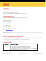
The board requires only a single +5V, 1.5 Amp or greater power supply to operate. An on board switching power supply
generates the necessary +15V, 120mA and –10V, 120mA power supplies from the 5V input. Although extensive filtering is
done on board, the power supplied to the board must be quiet and stable in order to achieve the best possible
performance.
(See Power Supply Modes, for an alternative way to power the board.)
INPUTS
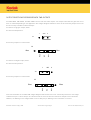
In the Free-Run mode, the evaluation board requires no input signals to begin acquiring images.
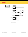
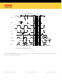
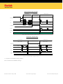
In Still mode, the evaluation board will acquire a single image on the falling edge of the Image_Acquire control line. This
can be accomplished via the push button (S4) or, remotely, by utilizing the Image_Acquire control line.
See Section Still/Free-Run Modes for more information on Still and Free-Run modes.
See Sections Line/Switches Modes and section AD_IN/EX Modes for information on additional optional inputs.
OUTPUTS
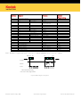
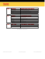
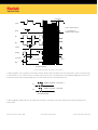
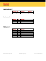
D[11..0] (+/-)
12 bits of Differential TTL Digital information
INTEGRATE
A signal provided to allow the user to synchronize the strobing of LED illuminators or opening of a
shutter, during the integration period.
FRAME (+/-)*
Differential TTL Frame grabber vertical sync signal.
LINE (+/-)*
Differential TTL Frame grabber horizontal sync signal.
PIX (+/-)*
Differential TTL Frame grabber pixel sync
Note: These sync signals can be modified if necessary to accommodate different Frame Grabbers.
JTAG PROGRAMMING
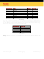
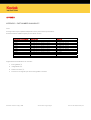
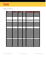
Altera 7000S In System Programmable (ISP) PLD’s are used on this board. A ten-pin header (J8) is provided to allow for
the programming of these PLD’s. Since these parts are re-programmable, custom digital logic can be implemented for
timing and mode adjustments or additions. Any custom implementation can be made quickly and easily to via the JTAG
programming interface provided by this connector.
©Eastman Kodak Company, 2008
www.kodak.com/go/imagers
Revision 8.0 MTD/PS-0215 p11