1
5 RAM500 Memory Expansion Module
Host Clock Logic
The host board provides four SDRAM clocks to the memory expansion connector. The
frequency of the RAM500 CLKS is the same as the host board.
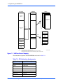
RAM500 Module Installation
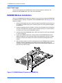
One or more RAM500 memory expansion modules can be mounted on top of the MVME5100
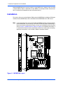
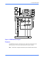
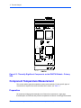
for additional memory capacity. To upgrade or install a RAM500 module, refer to Figure 5-2 and
proceed as follows:
1. Attach an ESD strap to your wrist. Attach the other end of the ESD strap to the chassis
as a ground. The ESD strap must be secured to your wrist and to ground throughout
the procedure.
2. Perform an operating system shutdown. Turn the AC or DC power off and remove the
AC cord or DC power lines from the system. Remove the chassis or system cover(s)
as necessary for access to the CompactPCI boards.
3. Carefully remove the MVME5100 from its VME card slot and lay it flat, with connectors
P1 and P2 facing you.
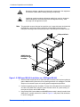
4. Inspect the RAM500 module that is being installed on the MVME5100 host board
(bottom configuration if two are being installed, top configuration if only one is being
installed) to ensure that standoffs are installed in the three mounting holes on the
module.
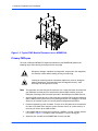
5. With standoffs installed in the three mounting holes on the RAM500 module, align the
standoffs and the P1 connector on the module with the three holes and the J16
connector on the MVME5100 host board and press the two connectors together until
they are firmly seated in place.
Figure 5-2. RAM500 Module Placement on MVME5100
46
MVME51005E Single Board Computer Installation and Use (6806800A38B)