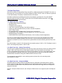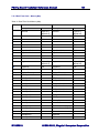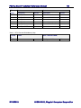
1
PC/II+p Board Technical Reference Manual
48
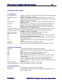
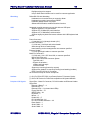
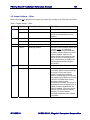
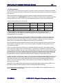
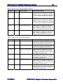
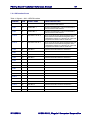
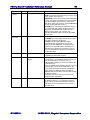
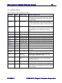
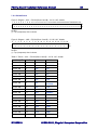
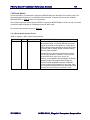
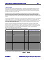
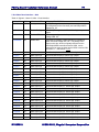
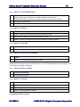
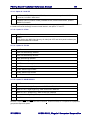
PIN NAME
PIN#
SIGNAL NAME
SIGNAL DESCRIPTION
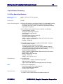
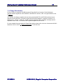
1-DIOR#
b5
IO Read Command
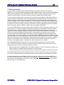
A1-DIOR#,A1-DDMARDY#,A1-HSTROBE
DIOR# is the strobe signal asserted by the host to read
device registers or the data port.
HDMARDY# is a flow control signal for Ultra DMA data
in bursts. This signal is asserted by the host to indicate
to the device that the host is ready to receive Ultra
DMA data in bursts. The host may negate HDMARDY#
to pause an Ultra DMA data in burst.
HSTROBE is the data out strobe signal from the host
for an Ultra DMA data out burst. Both the rising and
falling edge of HSTROBE latch the data from A1DD(15:0) into the device. The host may stop
generating HSTROBE edges to pause an Ultra DMA
data out burst.
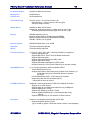
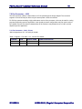
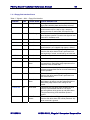
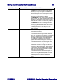
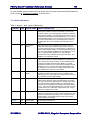
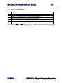
A1-DIOW#
c5
IO Write Command
A1-DIOW#,A1-STOP
A1-DIOW# is the strobe signal asserted by the host to
write device registers or the data port.
A1-STOP is the Stop Ultra DMA Burst signal.
A1-DIOW# shall be negated by the host prior to
initiation of an Ultra DMA burst. A1-STOP shall be
negated by the host before data is transferred in an
Ultra DMA burst. Assertion of A1-STOP by the host
during an Ultra DMA burst signals the termination of
the Ultra DMA burst.
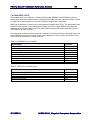
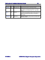
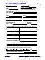
A1-DMACK#
e6
DACK for IDE Master
This signal is used by the host in response to
A1-DMARQ to initiate DMA transfers.
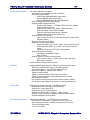
A1-DMARQ
d5
DMA Request for IDE
Master
This signal is used for DMA data transfers between
host and device. It is asserted by the device when it is
ready to transfer data to or from the host. For
Multiword DMA transfers, the direction of data transfer
is controlled by the
signals, A1-DIOR# and A1-DIOW#. This signal is used
in a handshake manner with A1-DMACK#, i.e., the
device shall wait until the host asserts A1-DMACK#
before negating A1-DMARQ, and re-asserting A1DMARQ if there is more data to transfer. When a DMA
operation is enabled,
A1-CS0# and A1-CS1# shall not be asserted and
transfers shall be 16-bits wide.
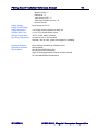
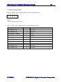
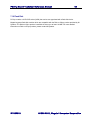
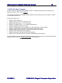
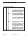
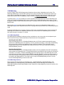
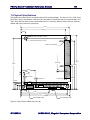
A1-IOCS16#
c6
Device 16-Bit I-O
This is the input pin from the IDE device which, during
PIO transfer modes 0, 1 or 2, indicates to the host
system that the 16-bit data port has been addressed
and that the device is prepared to send or receive a
16-bit data word.
MT002615
©1999-2001, Megatel Computer Corporation