1
SERVICING INSTRUCTIONS
REPLACING PARTS
9. boost element thermostat
8. HOBS
8.1
WARMING PLATE:
• Remove the four fixing screws and lift the plate from its
recess
• Pull the control knob off the spindle.
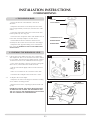
• Remove the four screws retaining the front panel,
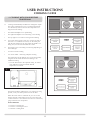
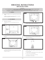
Diagram 8, Arrow B.
8
NOTE: WHEN REPLACING THE GAS AND ELECTRIC HOBS,
CLEAN THE EDGES OF BOTH THE COOKER TOP AND
THE HOBS PRIOR TO APPLYING THE SEALANT.1
8.2
GAS HOB:
• Isolate the gas supply to the hob
From inside the top-left oven:
• Remove the six screws securing the access plate, Diagram
7
AR1601
7
• Remove the two screws securing the control to the panel,
Diagram 9
9
retaining nut
AR1590
• Undo the gas connection at the loose joint through the
access panel in the top of the oven
In the top oven is a large retaining nut that secures the hob:
• Remove the nut and washer, Diagram 7
Using a sharp knife:
• Cut the seal around the edges of the hob
• Lift the front off the hob and draw it forward
approximately 150mm to gain access to the rear of the
ovens
8.3
ELECTRIC HOB:
To remove the electric hob, using a sharp knife:
• Cut the seal around the edges of the hob
• Lift the front off the hob and draw it forward
approximately 150mm to gain access to the rear of the
ovens
AR1591
Note the positions of all the wires and disconnect the
control. Alternatively, transfer each wire to the new
control individually.
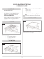
• Remove the two screws holding the oil valve cover,
Diagram 10, Arrow A.
10
28
B
B
B
B
A
A
AR1601
• Remove the phial from the bracket in the top of the oven
• Pull the capillary through the access tube. The thermostat
can now be removed.
• Reverse the order of the above procedure to reassemble.