1
BIOS and System Programming
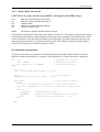
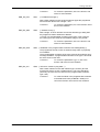
4.3.3
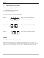
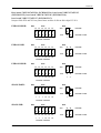
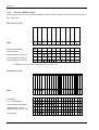
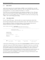
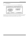
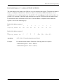
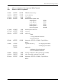
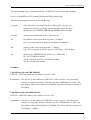
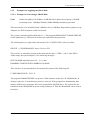
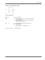
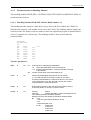
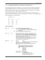
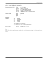
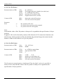
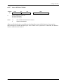
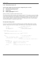
Control Register (I/O-Address 282 hex - write only)
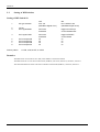
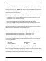
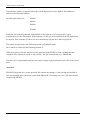
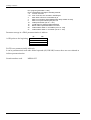
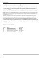
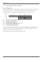
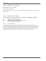
The bit 0 and bit 1 control the system reset:
bit 1
bit 0
0
0
1
1
0
1
0
1
reset by
watchdog
on
off
off
on*
reset by
RES key
off
on
off
on*
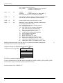
* The mode bit1 = 1 and bit0 = 1 can be used with the CP486 modules with level 2 or higher
(PCB board 5012V30 or higher)
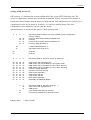
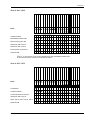
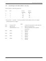
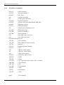
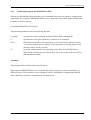
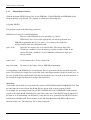
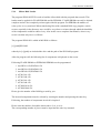
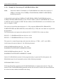
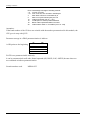
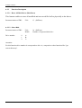
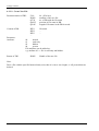
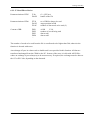
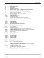
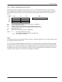
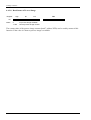
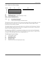
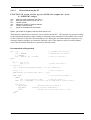
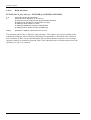
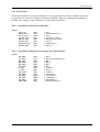
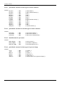
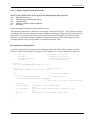
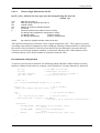
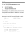
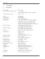
Status
Bit 2
Bit 3
interrupt to PLC
bank reset off
(from PCB 5012V17 on)
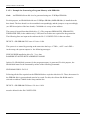
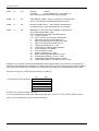
Bit 4
LED 1
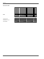
Bit 5
LED 2
Bit 6
LED 3
Bit 7
LED 4
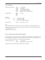
CP 486 ⋅ 00/14
0
1
0
connected to interrupt line on back plane bus
bank reset at system reset
bank reset off (bank can be responded
by the PLC)
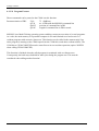
LED off
LED on
LED off
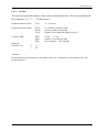
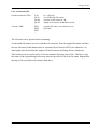
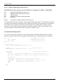
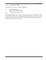
1
0
1
0
1
LED on
LED off
LED on
LED off
LED on
0
1
VIPA GmbH
65