1
RAS96 RASCard User Guide
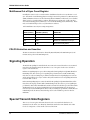
Multiframes Out of Sync Count Register
Normally this counter is used to count the number of multiframes that the receive synchronizer is out of
sync. This number is useful in ESF applications needing to measure the parameters Loss Of Frame Count
(LOFC) and ESF Error Events as described in AT&T publication TR54016. In this mode, it is not disabled
during receive loss of synchronization conditions. In the alternate operating mode, it will count either
errors in the Ft framing pattern (in D4 mode) or errors in the FPS framing pattern (in ESF mode). In this
mode, it is disabled during receive loss of synchronization conditions.
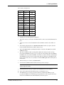
Table 4. Multiframes Out-Of-Sync Counting Arrangements
FRAMING
MODE (CCR2.3)
COUNT MOS OR F–BIT
ERRORS? (RCR2.0)
WHAT IS COUNTED IN THE
REGISTER
D4
MOS
Number of multiframes out of sync
D4
F–Bit
Errors in the Ft pattern
ESF
MOS
Number of multiframes out of sync
ESF
F–Bit
Errors in the FPS pattern
FDL/FS Extraction and Insertion
The SCT can extract/insert data from/ into the Facility Data Link (FDL) in the ESF framing mode, and
from/into Fs bit position in the D4 framing mode.
Signaling Operation
The Robbed–Bit signaling bits embedded in the T1 stream can be extracted from the receive stream and
inserted into the transmit stream by the SCT. There is a set of 12 registers for the receive side and 12
registers on the transmit side .
Each Receive Signaling Register reports the incoming Robbed–Bit signaling from eight DS0 channels. In
ESF framing mode, there can be up to four signaling bits per channel (A, B, C, and D). In D4 framing
mode, there are only two framing bits per channel (A and B). The Receive Signaling Registers are frozen
and not updated during a loss of sync condition. They will contain the most recent signaling information
before the “OOF” occurred.
Each Transmit Signaling Register contains the Robbed–Bit signaling for eight DS0 channels that will be
inserted into the outgoing stream if enabled. In ESF framing mode, there can be up to four signaling bits
per channel (A, B, C, and D). On multiframe boundaries, the SCT loads the values present in the Transmit
Signaling Register into an outgoing signaling shift register. In the ESF framing mode, the interrupt is
received every 3 ms. In D4 framing mode, there are only two framing bits per channel (A and B). However
in D4 framing mode, the SCT uses the C and D bit positions as the A and B bit positions for the next
multiframe.
Special Transmit-Side Registers
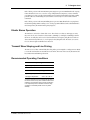
There is a set of seven registers in the SCT that can be used to custom tailor the data that is to be
transmitted onto the T1 line, on a channel-by-channel basis. Each of the 24 T1 channels can be either
forced to be transparent or to have an idle code inserted into them.
56
CommPlete Communications Server