1
GSM DATALOGGER DESCRIPTION
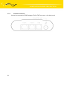
2.7.3.
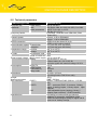
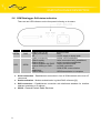
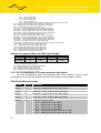
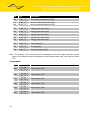
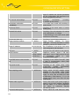
PWR supply connector
Panel socket RJ45
Pin
number
Signal
mark
1
I/O 5
Input/Output – analogue or binary input or binary
output (open collector)
Input/Output
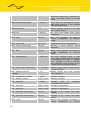
2
I/O 4
Input/Output – analogue or binary input or binary
output (open collector)
Input/Output
3
I/O 3
Input/Output – analogue or binary input or binary
output (open collector)
Input/Output
4
+12V
Output + 12V supply of other circuits (connected
directly to datalogger supply)
Output
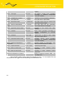
5
GND
Signal and supply ground
6
I/O 2
Input/Output – analogue or binary input or binary
output (open collector)
Input/Output
7
I/O 1
Input/Output – analogue or binary input or binary
output (open collector)
Input/Output
8
Description
Service For servicing purposes only
Direction
Input/Output
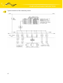
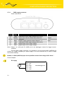
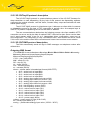
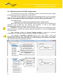
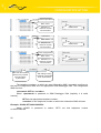
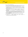
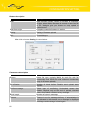
GSM Datalogger DA4 is equipped with user interface CIO for analogue signal reception
and processing and control (settings) of binary signals. User is provided with 5 adjustable
inputs/outputs located on CIO connector at the front panel.
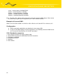
There are five signals linked to CIO that are possible to process and control by setting
up GSM Datalogger DA4. These signals can be controlled remotely, or their values can be
sent in data form to a remote point of data network.
16