1
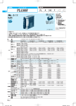
PLA300F
PLA
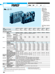
SPECIFICATIONS
CASE SIZE/WEIGHT
COOLING METHOD
WARRANTY WARRANTY
OTHERS
102X41X190mm [4.02X1.61X7.48 inches] (Excluding terminal block and screw) (WXHXD) / 1.0kg max
Forced cooling (internal fan)
5-year (Depends on the used condition)
*8
*6
*1 This is the value that measured on measuring board with capacitor
of 22mF and 0.1mF at 150mm from output terminal.
Measured by 20MHz oscilloscope or Ripple-Noise meter
(Equivalent to KEISOKU-GIKEN: RM103).
Please refer to the instruction manual 1.6.
*2 Drift is the change in DC output for an eight hour period after a
half-hour warm-up at 25C.
*3 Derating is required. As for DC input, 440Hz input and AC265 to
277V input, please contact us.
*4 Please contact us about dynamic load and input response.
*5 Derating is required. Please refer to instruction manual 3.2.
*6 As for detail condtion, please refer to instruction manual 3.3.
*7 Please contact us about safety approvals for the model with option.
*8 Fan speed is changed by load factor.
*9 Please contact us about other class.
*10 RC terminal is applied at option -R. And RC terminal is
isolated from input, output and FG.
* To meet the specifications, do not operate over-loaded
condition.
* Parallel operation is not possible.
* A sound may occur from power supply at peak loading.
Features
- Economical model
- Long lifetime (Refer to instruction manual)
- Low profile (41mm, 1.61 inch = meet to 1U height)
- Wide temperature range (-20 to +70 Refer to instruction manual)
- Screw hold type terminal block
- Fan speed control (At no load condition)
- Various option
- Complies with SEMI F-47 (Option-U: Refer to instruction manual)
Block diagram
FUSE
250V 10A
NOISE
FILTER
AC IN 85 - 264V
INRUSH
CURRENT
LIMIT
RECTIFIER
FG
CURRENT
SENSING
BOOSTER
INDUCTOR
RECTIFIER
AND
FILTER
CURRENT
SENSING
CONTROL
CONTROL
OVER VOLTAGE
PROTECTION
INVERTER
INVERTER
RECTIFIER
AND
FILTER
THERMAL
PROTECTION
THREE
TERMINAL
REGULATOR
CONTROL
DC OUT
FAN
External view
External size of option V, option R and option T2 is different from standard model, and refer to ”5. Option and Others” of instruction manual for detail.
±1.5
16.6
[0.65]
13.5
±1.5
(LED)
[0.53]
102
[0.2max]
150 ±0.5
[0.77]
[5.91]
AIR FLOW
[1.61]
[0.98]
5max
[7.48]
25 ±0.5
190
19.5
[4.02]
[2.36]
60 ±0.5
[5.91]
[0.77]
19.5
150 ±0.5
[0.49]
10.5
¶ Tolerance : ±1 [±0.04]
¶ Weight : 1.0kg max
¶ PCB Material/thickness : CEM-3 / 1.6mm [0.06inches]
¶ Chassis material : Aluminum
¶ Case material : Electric galvanizing steel board
¶ Dimensions in mm, [ ]=inches
¶ Mounting torque : 1.2N-m max
¶ Screw tightening torque : 1.6N-m max
¶ Please connect safety ground to FG terminal on the unit.
12.5
[0.41]
5.7
[0.22]
10
M4
4-M4
Mounting Hole
(Bottom sides)
41
[0.78]
Name plate
[0.79max]
[0.39]
19.8 ±1.5
5.75 ±1.5
20max
AC AC
-V FG (N) (L)
FG( )
AC(N)
AC(L)
+V +V -V
Output terminal (-)
V.ADJ
Output terminal (+)
[0.23]
Output voltage
adjustable potentiometer
(potentiometer)
8.6
LED
±1.5
[0.34]
13.3
[0.52]
4-M4
Mounting Hole
PLA-7