1
Hardware
Product Specifications
Input Specifications
LT-3201A
3.8"
QVGA
Monochrome
Sink Output
Model:LT3201-A1-D24-K
Monochrome
Source Output
Model:LT3201-A1-D24-C
Performance Specifications
LT-3201A
Display Type
Monochrome Amber / Red LCD
Display Colors/Shades
Backlight
General Specifications
International Safety Standards
Black and White (8 shades)
Amber / Red LED (When replacement is required, contact your local distributor.)
Conforming Standards
Display Resolution
Input Voltage
Rated Voltage
Effective Display Area
8 levels of adjustment available via touch panel
Brightness Control
Contrast Adjustment
8 levels of adjustment available via touch panel
Font Sizes
dots
dots
Voltage Endurance
Insulation Resistance
dots
dots
Surrounding Air Temperature
Ambient Humidity
Storage Temperature
40 Char. x 30 rows
40 Char. x 15 rows
Storage Humidity
20 Char. x 15 rows
Atmosphere
Air Pressure Resistance (Availment Altitude)
Pollution Degree
10 Char. x 7 rows
Resistive Film (Analog)
Touch Panel Resolution
Internal Memory
FLASH EPROM 6MB *3
Backup Memory
Variable Area
SRAM 128KB *4
SRAM 64KB *4
Program Area
FLASH EPROM 132KB *5
Noise Immunity
(via noise simulator)
Electrostatic Discharge Immunity
15,000 steps*6
Number of Step
Grounding
External Dimensions
Weight
Serial
−
USB
USB 1.1 Connector: Type A x 1, Power Supply Voltage: DC5V 5%,
Output Current: 500mA (max.), Communication Distance: 5m (max.)
Sink / Source Input: 12 points, Source Output: 6 points
Connector: 22 pins
To mount EX Modules *7
To mount CANopen Master Unit *7
EX Module (EXT1)
AUX / Expansion Unit (EXT2)
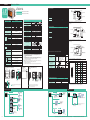
[External Dimensions / Interfaces]
Unit:mm [in.]
AUX/Expansion Unit (EXT2)
Interface
USB(host) Interface
Allowable Panel Thickness:
1.6 [0.06] to 5.0 [0.20]
Input
Input Points
The maximum thickness when two EX modules are connected:
96.8 mm [3.81 in.]
(Sink Type)
Unit: mm [in.]
above will change. The dimensions given here are representative
values and are intended for reference only.
OUT4 B11
OUT3 A10
OUT2 B10
OUT1 A9
OUT0 B9
Internal Circuit
0.5ms or less (with output DC24V, 200mA)
0.5ms or less (with output DC24V, 200mA)
L
L
* For faster response with light load use an external dummy resistance.
(Source Type)
Fuse 2.5A
Pulse Catch
DC24V
Open Collector
IN0, IN2,
IN4, IN6
OUT4 B11
OUT3 A10
OUT2 B10
OUT1 A9
OUT0
B9
L
Internal Circuit
+
-
DC24V
External
Power Supply
OUT0 to 3 only
Dummy Resistance*
0V A8
* For faster response with light load use an external dummy resistance.
User Defined
User Defined
t
+24V B8
OUT5
A11
L
Internal Circuit
1 Phase
Pin Connection
t
90 degree phase differential 2-phase signal /
1-phase +directional signal
50Kpps
Not Available
32-bit UP / DOWN Counter
Set through software
Not Available
Available
IN3, IN7
None
100Kpps
Available
−
−
−
−
−
−
−
−
−
Pulse / PWM Output Specifications
Load Voltage
Minimum Load Current
Maximum Output Frequency
Pulse Acceleration
ON Duty
DC24V
External
Power Supply
- +
[Output Circuit]
Input signal ON width
Output Points
0V A8
OUT0 to 3 only
Dummy Resistance*
User Defined
High Speed Count Frequency
Count Edge Designation
Count
Register
Counter Mode
Change
Upper / Lower Limit Settings
Preload/Prestrobe
Marker Input (Clear Counter Value)
Depending on type of connection cable used the dimensions shown
Fuse 2.5A
Minimum Pulse Width
(Pulse Input)
Output Method
DIO Interface
Dotted area indicates the cable diagram with sink output type devices.
[Output Circuit]
1mA (Pulse / PWM Output Unavailable)
High-speed Counter
DC24V Open Collector
Single phase (4 points)
Double phase (1 or 2 points)
Use CT0 (IN0),
CT0(IN0),
CT1(IN2) in pairs.
CT1(IN2),
CT0: Phase A, CT1: Phase B
CT2(IN4),
CT2(IN4),CT3(IN6) in pairs.
CT3(IN6),
CT2: Phase A, CT3: Phase B
Phase
4/R3 [0.12]
or less
+0.04
+1
]
92.5 - 0 [3.64 - 0
92 [3.62]
21.5[0.85]
5 [0.20]
21.5 [0.85]
104 [4.09]
Display/Touch Panel
+1
+0.04
118.5 -0 [ 4.67 - 0 ]
EX Module (EXT1)
Interface
Internal Circuit
OUT5 A11
Count Speed
(Rise, Fall Time)
[Cable Attached Dimensions]
Unit: mm [in.]
76.5 [3.01]
130 [5.12]
Internal Circuit
IN11 A6
IN10 B6
IN9 A5
IN8 B5
IN7 A4
IN6 B4
IN5 A3
IN4 B3
IN3 A2
IN2 B2
IN1 A1
IN0 B1
Internal Circuit
High-speed Counter / Pulse Catch Input Specifications
*1 Korean, Chinese (Simplified) and Chinese (Traditional),Cyrillic and Thai character support. For more information,
see the operation environment for GP-Pro EX.
*2 Using the software, you can resize characters.
*3 User area.
o
*4 Service life of lithium battery is 10 years or more at a battery ambient temperature of 40 C or less,
4.1 years or more at 50oC or less, 1.5 years at 60oC or less. The backup period is about 100 days after
the initial charge (fully charged), and about 6 days up to the end of battery life.
*5 Using Pro-face s Step counting method.
*6 Up to 60,000 steps can be made, but this reduces the capacity of the internal screen data memory by
1MB.
*7 EX Module and CANopen Master Unit cannot be used at the same time.
*8 Temperature in and around the panel.
*9 Confirmed compatibility under conditions. This does not guarantee compatibility for all environments.
[Panel Cut-out]
- +
+24V B8
Rated Voltage
Allowable Voltage
Sink Output
Output Method
Source Output
Maximum Load Voltage
Minimum Load Current
Output Voltage Drop
OFF to ON
Output Delay Time
ON to OFF
Voltage Leakage (When OFF)
Clamp Voltage
Type of Output
Common Lines
Common Design
External Connection
Output Protection Type
Internal Fuse
Surge Control Circuit
Output Points
Output Signal Display
Isolation Method
External Power Supply
Cooling Method
Sink / Source Input: 12 points, Sink Output: 6 points
Connector: 22 pins
Sink Output
Control (Model: LT3201-A1-D24-K)
(Built-in DIO) Source Output
(Model: LT3201-A1-D24-C)
*9
Ratings
−
Ethernet
Interface
Vibration Resistance
82 [3.23]
98 [3.86]
Touch Panel Type
Control Memory
*8
86 [3.39]
Text
COM
+ - B7
OUT4 to OUT15
Power Consumption
dot
Stroke font: 6 to 127 dot fonts
Standard font: Width and Height can be expanded up to 8 times.*2
Character Sizes
DC24V
External
Power supply
Output Specifications
Allowable Voltage
Japanese: 6,962 (JIS Standards 1 & 2 including 607 non-kanji characters)
ANK: 158 *1
Language Fonts
[Input Circuit]
DC24V
DC28.8V
Sink / Source Input
6.5mA (DC24V) (IN0, IN2, IN4, IN6) 5mA (DC24V) (Other inputs)
Approx.3.7k (IN0, IN2, IN4, IN6) Approx.4.7k (Other inputs)
12
1
12 points / 1 common line
DC19V or more
DC5V or less
0.5 to 20ms *10
0.5 to 20ms *10
No LED indicators
Photocoupler Isolation
22-pin connector (used with Output section)
For Signal: DC24V
Rated Voltage
Maximum Allowable Voltage
Input Method
Rated Current
Input Resistance
Input Points
Common Lines
Common Design
ON Voltage
Operation Range
OFF Voltage
OFF to ON
Input Delay Time
ON to OFF
Input Signal Display
Isolation Method
External Connection
External Power Supply
Pulse
PWM
4 points
PLS0 to PLS3 (OUT0 to OUT3) PWM0 to PWM3 (OUT0 to OUT3)
User Defined
User Defined
DC24V
1mA
Max.65kHz(set through software)Varies depending on the number of CH of High-speed counter, pulse output
Available
Not Available
50% 10% (at 65kHz)*11
19 to 81% (at 65kHz) *12
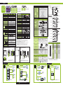
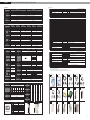
[System Structure]
A1
A11
B1
B11
(Cable Side)
Pin No.
Signal Name
Pin No.
Signal Name
A1
IN1
B1
IN0(CT0)
A2
IN3
B2
IN2(CT1)
A3
IN5
B3
IN4(CT2)
A4
IN7
B4
IN6(CT3)
A5
IN9
B5
IN8
A6
IN11
B6
IN10
A7
NC
B7
COM
A8
0V
B8
+24V
A9
OUT1 (PLS1, PWM1)
B9
OUT0 (PLS0, PMW0)
A10
OUT3 (PLS3, PWM3)
B10
OUT2 (PLS2, PWM2)
A11
OUT5
B11
OUT4
*10 Digital filter can be set intervals of 0.5ms.
*11 The ON duty error (10%) reduces as the output frequency setting is lower.
*12 ON duty (effective range) increases as the output frequency setting is lower.
[Editor Environment]
USB Interface
Barcode Reader*1
DIO Interface
Various I/O devices,
indication lights,
LED sensors,
switches, etc.
(Commercial type)
USB Storage*1
(Commercial type)
USB-IEEE1284
Conversion Cable
(Commercial type)
DIO Cable
DIO Connector
(Provided by the user)
(included in the package)
(Commercial type)
CA3-USBCB-01
Various I/O devices,
indication lights,
LED sensors,
switches, etc.
FP-US00 or Commercial type
Modem *1
(Commercial type)
PC
(Commercial type)
Screen Creation Software
GP-Pro EX
EX Module Interface (EXT1)
USB Cable
USB-Serial (RS-232C)
Conversion Cable
USB Transfer Cable
CA6-DIOCN4-01
Printer *1
USB Interface
USB Storage
EX Module
(max.2 units)
With the memory loader tool, the screens can be
transferred via USB storage.
(Commercial type) *1
CA6-USB232-01
USB Front Cable
Barcode Reader*1
CA5-USBEXT-01
(Commercial type)
USB Hub
(Commercial type)
CANopen Master Unit
09
Transfer Cable
(CANopen standards)
Commercial type
Slave Unit
for CANopen *1
*1 For supported models, refer to Pro-face’s support site "Otasuke Pro!"(http://www.pro-face.com/otasuke/).
*2 EX Module and Expansion unit cannot be used at the same time.
10