1
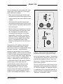
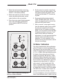
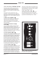
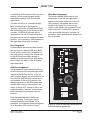
Model 750 The monitor source push-button switches were chosen to allow more than one source to be selected at a time. The ability to simultaneously depress and lock multiple buttons is not a glitch, but is a feature which can prove useful in some specialized situations. An example is where a mix-minus cue signal from a remotelylocated facility is being returned to the Model 750 by means of external monitor input 1. By selecting both EXT 1 and main stereo, a composite signal is created for monitoring. Monaural Function A function is provided that allows the selected monitor source to be combined to form a monaural signal. The monaural function is useful for checking a stereo audio signals image across the left/right field, as well as determining its monaural compatibility. When the stereo/mono button is in the mono (in) position, the left and right channels of the monitor source are combined (summed) and the level of the summed signal is dropped by 6dB. The 6dB level reduction is a standard part of the monaural function on virtually all audio consoles, preventing level buildup caused by the summing of phase coherent signals. The monaural function does not impact the main and AUX audio buses, affecting only the monitor speaker output, headphone output, and the meters. Note that the monaural function effects the monitor source selected by the push-button switches, as well as, if configured and active, the AUX interrupt signal. Metering Two VU-type meters and associated LEDs are provided for visual level monitoring. The meters provide the operator with an Model 750 User Guide Studio Technologies, Inc. excellent sense of the average signal level, while the LEDs display peak signal conditions. A peak LED lights whenever the level of the signal being monitored reaches within 6dB of the maximum internal bus level. In the real world, audio material with large transient information may only display a moderate signal level on the VU meters. While the fast response time of the peak LEDs will allow the presence of such transients to be displayed. A push-button switch, located at the top of the monitor section, allows the audio source for the meters to be selected. When the button is in the main (out) position the left channel of the main audio bus is sent to the left meter, the right channel of the main audio bus is sent to the right meter. When the button is in the monitor (in) position the monitor source selected for the speaker and headphone outputs is connected to the meters. Reviewing the ramifications of the meter source button may prove useful; we do so in the following paragraphs: Allowing the meters to directly monitor the main audio bus is provided for operator peace-of-mind. It allows a continuous display of what is, in most situations, the on-air audio bus, no matter what is happening in the monitor section. Note that when the meter source button is set to the main (out) position, use of the stereo/ mono button will have no impact on the meters. Activation of the AUX interrupt function wont affect the meters either. With the meters selected to observe the monitor source, great flexibility is possible. However, unless a full understanding of how the meters function in this mode is gained, the flexibility can be accompanied by confusion! Issue 3, May 1997 Page 33