1
OBJ_BUCH-1038-003.book Page 15 Friday, August 17, 2012 10:59 AM
English | 15
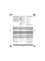
Noise/Vibration Information
Measured noise values determined according
to EN 12549.
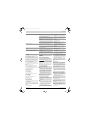
Typically the A-weighted noise levels of the pneumatic tool
are: Sound pressure level 96 dB(A); sound power level
110 dB(A). Uncertainty K=2 dB.
Wear hearing protection!
Vibration total values ah and uncertainty K determined according to EN ISO 20643: ah < 2.5 m/s2, K= 1.5 m/s2.
Declaration of Conformity
We declare under our sole responsibility that the product
described under “Technical Data” is in conformity with the
following standards or standardization documents:
EN 792 according to the provisions of the directive
2006/42/EC.
Technical file (2006/42/EC) at:
Robert Bosch GmbH, PT/ETM9,
D-70745 Leinfelden-Echterdingen
Dr. Egbert Schneider
Helmut Heinzelmann
Senior Vice President
Head of Product Certification
Engineering
PT/ETM9
Robert Bosch GmbH, Power Tools Division
D-70745 Leinfelden-Echterdingen
Leinfelden, 16.08.2012
Assembly
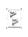
Connecting the Air Supply (see figure A)
Make sure that the pressure of the compressed-air system
is below the maximum permitted rated pressure of the
pneumatic tool. Firstly, set the air pressure to the lower
value of the recommended rated pressure (see “Technical
Data”).
When in doubt, check the pressure at the air inlet with a
pressure gauge with the pneumatic tool switched on.
For maximum performance, the values for the supply-air
hose 17 (connection thread, maximum operating pressure, inner hose diameter, maximum hose length; see
“Technical Data”) must be observed.
The compressed air supplied should be free of foreign material and moisture to protect the tool from damage, contamination, and the formation of rust.
All fittings, connecting lines and hoses must be dimensioned for the pressure and the required air volume.
Avoid restrictions in the air supply, e.g., from pinching,
kinking, or stretching!
Connecting the Air Supply to the Pneumatic Tool
– Empty the magazine 8.
(See “Emptying the Magazine”, page 15)
For the following worksteps, a fastener can be discharged when interior parts of the pneumatic tool are
not in the starting position due to repairs, maintenance
or transport.
– Connect the air connector 6 with a supply-air hose 17
equipped with an air-connection coupling 16.
– Check the proper function by placing the outlet 13 or
the rubber workpiece protector 1 of the pneumatic tool
onto a piece of scrap wood or wood material, and discharging once or twice.
Loading the Magazine
Disconnect the air supply before making
any adjustments, changing accessories,
or placing the pneumatic tool aside. This
safety measure prevents accidental starting of the pneumatic tool.
f Use only original Bosch accessories (see “Technical
Data”). The precision parts of the pneumatic tool such
as the magazine, the outlet and the shot duct are
matched to Bosch staples, nails and brads. Other manufacturers use other steel qualities and sizes.
Using fasteners not permitted, can damage the pneumatic tool and cause injuries.
Bosch Power Tools
While loading the magazine, hold the pneumatic tool in
such a manner that the outlet 13 is not pointed at your own
body or at other persons.
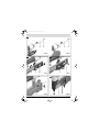
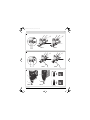
GTK 40 (see figures B1–B2)
– Pull back the magazine slider 11 until the button of magazine-slider lock 7 fully engages.
– Clean and lubricate the magazine slider 11 as required
and make sure that the magazine 8 is not dirty/soiled.
– Place a fitting strip of staples 18 over magazine 8.
The staple heads must face completely flush against the
surface of the magazine and the staple strips must move
easily in the magazine.
– Lightly pull back magazine slider 11 and press the button of magazine-slider lock 7 inward.
– Carefully guide the magazine slider to the front until it
touches the staple strip.
Note: Do not let the magazine slider snap back without
guiding it. Otherwise, the magazine slider could become
damaged, and there is danger of your fingers being caught
or pinched.
GSK 50 (see figures C1–C2)
– Press magazine lock 14 and at the same time pull magazine 8 toward the rear to the stop.
– Clean and lubricate magazine rail 20 as required.
– Insert a fitting nail strip 19.
If possible, the nail tip should touch the magazine rail
20.
– Slide the nail strip in the magazine all the way to the
front.
– Insert the magazine until magazine lock 14 engages
again.
Refill the magazine when the red bars of refill indicator 15
can be seen halfway.
Operation
Actuation systems
The pneumatic tool can be operated with two different actuations systems:
– Single actuation with safety run
With this actuation system, the discharge lock-off 2
must first be firmly pressed against the workpiece. A
fastener is not discharged until the trigger 10 is pulled.
Afterwards, further discharging procedures can only be
actuated, when the trigger and the discharge lock-off
have first been set back to the starting position.
– Contact actuation
With this actuation system, the trigger 10 must be
pulled first. A fastener is always discharged when the
discharge lock-off 2 is firmly pressed against the workpiece while the trigger is pressed.
This enables a higher working speed to be achieved.
The actuation system is set via the selector switch 9.
Starting Operation
Disconnect the air supply before making
any adjustments, changing accessories,
or placing the pneumatic tool aside. This
safety measure prevents accidental starting of the pneumatic tool.
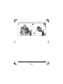
Working with Single Actuation (see figure D)
– Press selector switch 9 inward and at the same time pivot it to the bottom position until it engages.
The actuation system “single
actuation” is set.
– Release the selector switch 9 again.
– Firmly position the outlet 13 or the rubber workpiece
protector 1 on the workpiece until discharge lock-off 2
is pressed in completely.
– Afterwards, briefly press trigger 10 and release again.
A staple (GTK 40) or a brad (GSK 50) is discharged.
– Allow the pneumatic tool to bounce back from the workpiece.
– For another driving procedure, completely lift the pneumatic tool from the workpiece and position it firmly at
the next desired location.
Working with Contact Actuation (see figure E)
– Press selector switch 9 inward and at the same time pivot it to the upper position until it engages.
The actuation system
“contact actuation” is
set.
– Release the selector switch 9 again.
– Press and hold the trigger 10.
– Firmly position the outlet 13 or the rubber workpiece
protector 1 on the workpiece until discharge lock-off 2
is pressed in completely.
A staple (GTK 40) or a brad (GSK 50) is discharged.
– Allow the pneumatic tool to bounce back from the workpiece.
– For another driving procedure, completely lift the pneumatic tool from the workpiece and position it firmly at
the next desired location.
– Move the pneumatic tool uniformly over the workpiece
by lifting it off and applying it again.
Each time when applying the pneumatic tool while the
discharge lock-off is pressed in, a staple (GTK 40) or a
brad (GSK 50) is discharged.
– As soon as the desired amount of staples (GTK 40) or
brads (GSK 50) have been driven in, release trigger 10
again.
Working Advice
Disconnect the air supply before making
any adjustments, changing accessories,
or placing the pneumatic tool aside. This
safety measure prevents accidental starting of the pneumatic tool.
Check the proper function of the safety and actuation devices, and the tight seating of all screws and nuts each time
before using.
Disconnect a defective or not properly operating pneumatic tool immediately from of the air supply and contact an
authorised service agent for Bosch power tools.
Do not perform any incorrect manipulations on the pneumatic tool. Do not disassemble or block any components of
the pneumatic tool, such as the discharge lock-off.
Do not carry out “emergency repairs” with unsuitable
means. The pneumatic tool is to be maintained regularly
and properly (see “Maintenance and Cleaning”, page 16).
Avoid any weakening and damage whatsoever of the pneumatic tool, e.g., through:
– Imprinting or engraving,
– Retrofitting measures not approved by the manufacturer,
– Guiding along templates manufactured of hard material,
e.g. steel,
– Dropping on or sliding over the floor,
– Using as a hammer,
– Applying any kind of force.
Make sure to check whatever is below or behind your workpiece. Do not shoot staples (GTK 40) or brads (GSK 50) into walls, ceilings or floors, when persons are behind them.
The fasteners can burst through the workpiece and injure
someone.
Do not shoot a staple (GTK 40) or brad (GSK 50) on already driven-in fasteners. This could cause the fastener to
deform, the fasteners could become jammed or the pneumatic tool could move uncontrolled.
When the pneumatic tool is used under cold ambient conditions, the first staples (GTK 40) or brads (GSK 50) are
driven in slower than usual. Once the pneumatic tool has
warmed up during working, normal operating speed will be
regained.
Avoid blank shots in order to reduce the wear of the impact
striker.
For longer work breaks or after finishing work, disconnect
the pneumatic tool from the air supply and empty the magazine.
Emptying the Magazine
GTK 40
– Pull back the magazine slider 11 until the button of magazine-slider lock 7 fully engages.
– Remove staple strip 18.
1 609 929 U13 | (17.8.12)