1
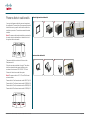
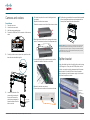
Power outlets in cable wells
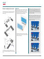
You may install power outlets for personal computers in
the cable wells. The exact look of the power outlet socket
itself will be country-specific, but this will not affect the
installation procedure. The socket comes with the cable
installed.
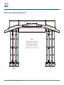
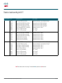
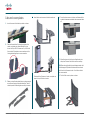
Left and right monitor cable wells
1
2
3
4
3
4
5
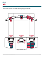
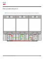
Note! The power outlet sockets installation procedure for
the center monitor cable wells is not identical to that of
the right and left monitor wells.
Left
Center
Right
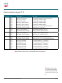
The power outlet kits are located in 6 boxes in the
Telepresence kit.
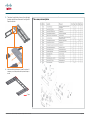
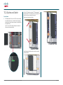
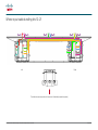
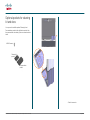
Center monitor cable wells
1
2
Follow the procedure outlined to the right. The cables
shall be connected to the power distribution units
as shown in the document “78-20195-01 T3 Cable
Schematics”, which comes with the system.
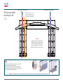
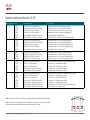
Note! The power outlets in L2, C1, C2 and R2 will need
extension cables.
Power outlet in L2 will use extension cable 129627 (kit 12)
Power outlet in C1 will use extension cable 129628 (kit 13)
Power outlet in C2 will use extension cable 129629 (kit 16)
Power outlet in R2 will use extension cable 129630 (kit 17)
L1
L2
C1
C2
R1 R2
78-19803-02 Cisco TelePresence System T3 System Assembly Guide, December 2011
Page 11 of 28