1
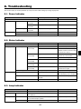
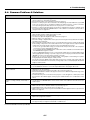
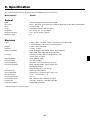
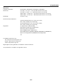
1. Introduction
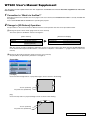
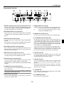
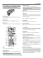
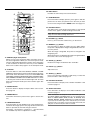
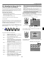
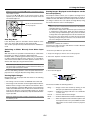
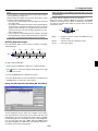
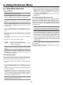
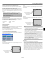
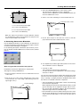
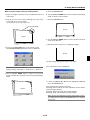
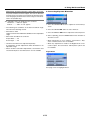
Terminal Panel Features
10
11
14
REMOTE PCCONTROL
IN
AUDIO IN
15
13
PC CARD
VIDEO IN
12 4
USB
2 6
AUDIO IN
AUDIO OUT
DVI-I
RGB
S-VIDEO IN
DVI-I IN
RGB IN
RGB OUT
7
3
1
5
L
/MONO
R
9
8
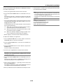
1. RGB IN / Component Input Connector (Mini D-Sub 15 Pin)
9. VIDEO AUDIO IN Jacks (RCA)
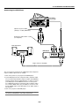
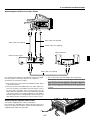
Connect your computer using the supplied RGB cable. This
connector also supports a component signal and SCART output signal. See page 2-4 for more details.
L/MONO: This is your monaural or left channel audio input
for stereo sound coming from the VIDEO source.
R:
This is your right channel audio input for stereo
sound from the VIDEO source.
2. RGB AUDIO IN Mini Jack (Stereo Mini)
This is where you connect audio output from your computer
or DVD player. A commercially available audio cable is required.
10. REMOTE IN Jack (Mini Jack)
Connect your remote control cable here for wired operation.
11. PC CONTROL Port (Mini DIN 8 Pin)
3. DVI-I IN Connector (DVI-I 24 Pin)
Use this port to connect your PC to control your projector via
a serial cable. This enables you to use your PC and serial
communication protocol to control the projector. The NEC optional serial cable (CA03D) is required to use this port. You
can also control the projector by using Dynamic Image Utility
2.0 included on the supplied CD-ROM.
Connect a computer with a DVI output using the supplied DVID cable.
This connector can be used to accept digital and analog signal output from a computer with a DVI connector.
4. DVI-I AUDIO Input Mini Jack (Stereo Mini)
To do so you must first have Dynamic Image Utility 2.0 installed on your PC. If you are writing your own program, typical PC control codes are on page 10-4. A cap is put on the
port at the factory. Remove the cap when using the port.
This is where you connect the audio output from your computer when connected to the DVI input. A commercially available audio cable is required.
12. USB Port (Type B)
5. RGB OUT Connector (Mini D-Sub 15 Pin)
Connect this port to the USB port (type A) of your PC using
the supplied USB cable. You can operate your computer's
mouse functions from the remote control.
You can use this connector to loop your computer image to
an external monitor from the RGB input source.
6. AUDIO OUT Mini Jack (Stereo Mini)
13. USB Port (Type A)
Connect an additional audio equipment here to listen to audio
coming from your computer, Video or S- Video input.
Connect a commercially available mouse that supports USB.
You can operate the menu or Viewer with the USB mouse via
this port.
Note that there is no audio output from this jack during Standby
and Idle.
Note that this port should not be connected to a computer
and that there may be some brands of USB mouse that the
projector does not support.
7. S-VIDEO IN Connector (Mini DIN 4 Pin)
Here is where you connect the S-Video input from an external
source like a VCR.
14 . PC CARD Slot
NOTE: S-Video provides more vivid color and higher resolution than
the traditional composite video format.
Insert a PC card, commercially available LAN card or NEC
optional wireless LAN card here.
8. VIDEO IN Connector (RCA)
15. PC CARD Eject Button
Connect a VCR, DVD player, laser disc player, or document
camera here to project video.
Press to eject a PC card partially.
1-5