1
User Manual PolyGard® MGC-03
Page 20
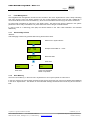
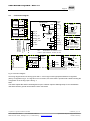
3.7.5
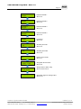
Customer Password (Code 4)
Change the system password for level 4
3.7.6
Symbol
Description
Default
Status
Function
XXXX
Customer
Password
XXXX
XXXX = Definition of an individual 4-digit customer’s password
(level 4)
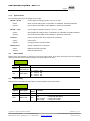
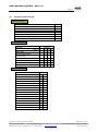
Analog Output
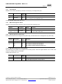
The Gas Controller has one analog output (AO) with a (0)4 to 20 mA / (0)2 to 10 V signal. The signal of one or two
measuring points can be assigned to the analog output. The assignment is effected in the menu “MP Parameters”
for each MP. The measuring point sends the signal as defined in the menu “C/A Mode“ (CV or AV).
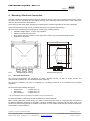
The output signal (mA / V) and starting point (0 /20%) is selected at the I/O Board by means of jumpers. See fig. 4.
Out of the signals of all assigned measuring points the Gas Controller module determines the minimum, the
maximum or the average value and transmits it to the analog output. The definition, which value is transmitted, is
effected in the menu “Analog Output 1“.
The analog output can be calibrated at 4 and at 20 mA, only in mA mode. Therefore an ampere meter (measuring
range 25 mA) can be attached to the AO and the respective factor has to be changed until the analog output
corresponds to 4 and/or 20 mA. During calibration evaluation of the measuring point signals is not possible. This
calibration is effected by the factory. The factors shall not be changed.
3.7.7
Default
Status
Symbol
Description
Max.
Select
Max.
Output Mode
4.0
20.0
Calibration
4.0
20.0
Function
Min.
= Displays the minimum value of all assigned MP
Max.
= Displays the maximum value of all assigned MP
Average = Displays the average value of all assigned MP
4.
20.0
= Calibration factor at 4 mA
= Calibration factor at 20 mA
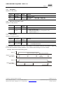
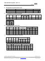
Define the Failure Relay
Definition of the failure relay. See also fault management (3.1)
3.7.8
Symbol
Description
04
Fault Relay
Default
Status
R04
Function
R04 = Define the fault relay
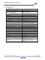
Power On Time
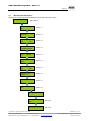
Gas sensors need a running-in period, until the chemical process of the sensor reaches stable conditions. During
this running-in period the current signal can lead to an unwanted releasing of a pseudo alarm. Therefore the power
on time is started at the Gas Controller module after having switched on the power supply. While this time is
running out, the Gas Controller does not activate any alarms. The power on status occurs in the starting menu.
Symbol
Description
30 s
Power On Time
Default
Status
30 s
Function
XX = Define the power on time (sec.)
PolyGard is a registered trademark of MSR
Phone: 0049(0)8531/9004-0
Fax: 0049(0)8531/9004-54
MSR-Electronic GmbH, Würdinger Str. 27, D 94060 Pocking
GAMGC03_E_0115
www.msr-electronic.de
Specification subject to change without notice.
Printed in Germany