1
PLC WorkShop for Modicon
Chapter 11 – Instructions, Transfer and move instructions
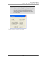
WARNING: The XOR function overrides the disable state of a coil used in
the destination node of the function block. This can cause
personal injury if the user assumes a coil has disabled an
operation and repairs are being made, because the coil's state can
change as a result of the XOR function.
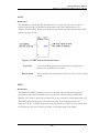
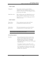
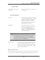
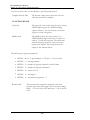
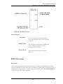
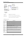
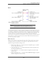
Bottom Node
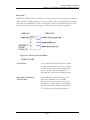
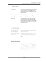
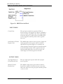
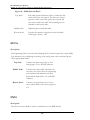
The bottom node contains the numerical value
that specifies the matrix length for both matrices.
This constant can range from 1 to 100. 1 equals a
group of 16 bits, 2 equals a group of 32 bits, and
so on.
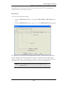
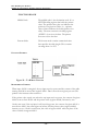
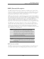
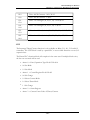
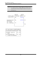
EXAMPLE XOR INSTRUCTION
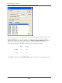
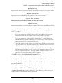
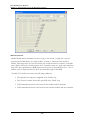
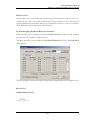
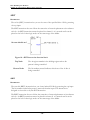
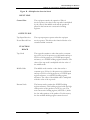
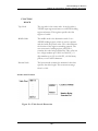
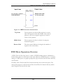
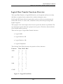
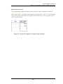
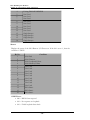
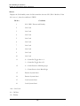
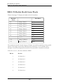
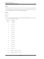
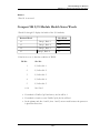
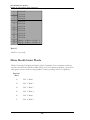
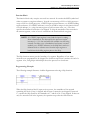
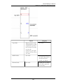
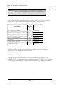
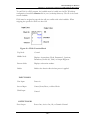
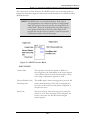
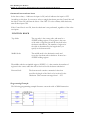
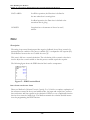
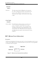
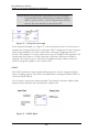
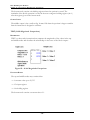
If bits 1 - 4 in register 30026 are 0011, and bits 1 - 4 in 40206 are 0101, the result placed
in register 40206 is 0110 (see "Figure 43").
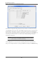
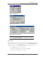
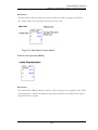
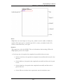
Figure 43 – Logical XOR Operation
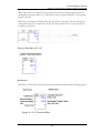
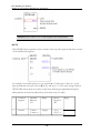
PROGRAMMING EXAMPLE
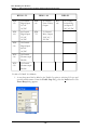
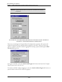
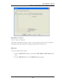
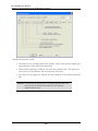
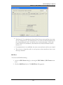
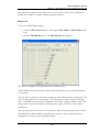
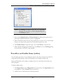
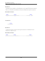
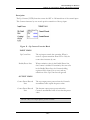
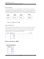
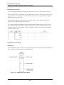
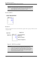
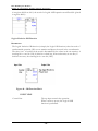
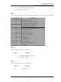
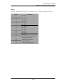
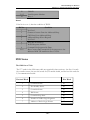
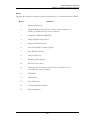
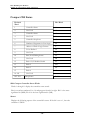
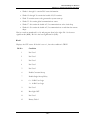
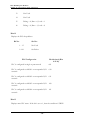
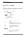
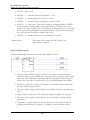
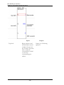
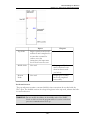
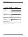
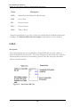
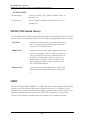
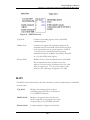
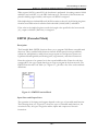
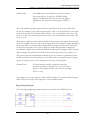
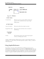
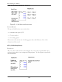
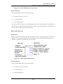
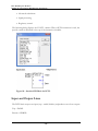
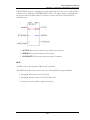
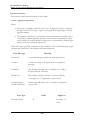
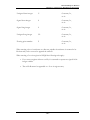
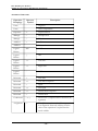
This example illustrates a network with a Logical XOR function.
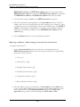
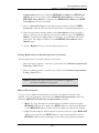
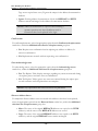
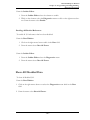
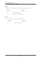
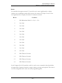
When input 10106 is energized, the top input receives power. A Logical Exclusive OR is
performed between the bit patterns in registers 30026-30031 and 40206-40211. The
- 502 -