1
5. BOARD CONFIGURATION
Refer to the Drawing of Diamond-MM-32X-AT on page 6 for locations of the configuration items
mentioned here.
5.1 Base Address
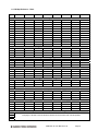
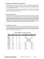
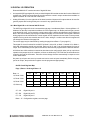
Each board in a PC/104 system must have its own unique block of addresses that does not overlap with
any other board in the system or feature on the CPU. The lowest address of this address block is called
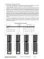
the base address. Diamond-MM-32X-AT's base address is set with 3 pairs of pins marked “ADDR” on pin
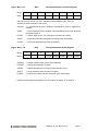
header J7, located near the PC/104 bus connectors. The table below lists the 8 possible jumper
configurations and the corresponding base addresses.
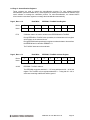
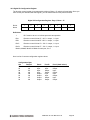
Base Address Configuration
Base Address Pin Header J8 Configuration
Hex
140
340
100
180
200
280
300
380
Decimal
320
832
256
384
512
640
768
896
C
Installed
Installed
Installed
Installed
Open
Open
Open
Open
B
Installed
Installed
Open
Open
Installed
Installed
Open
Open
A
Installed
Open
Installed
Open
Installed
Open
Installed
Open
Default Setting
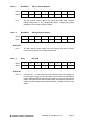
5.2 Interrupt level
Interrupts are used for hardware I/O operations that are independent of normal program flow. DiamondMM-32X-AT can be set up to generate interrupts under several circumstances. The most common use of
interrupts is to transfer A/D data from the board to system memory during high-speed A/D sampling. The
board can also generate interrupts to transfer digital data into or out of the board, as well as at regular
intervals according to a programmable timer on the board. Individual control bits are used to enable each
type of interrupt.
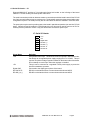
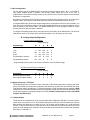
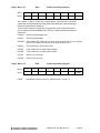
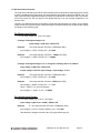
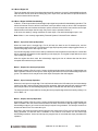
Jumper block J7 contains pins for selecting the interrupt level. To set the desired level, install a jumper
under that level’s IRQ number and also in the R position. The R position connects a 1KΩ pull-down
resistor to the selected IRQ line to allow the board to share the IRQ level with another board in the
system. Note that only one pulldown resistor should be installed on any IRQ level. If you have another
board in the system using the same IRQ level as Diamond-MM-32X-AT, and that board has the pulldown
resistor already configured, then remove the jumper from the R position on J7.
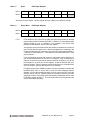
5.3 DMA level
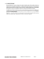
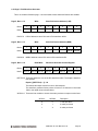
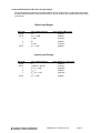
Jumper block J7 contains pins for selecting the DMA level between channels 1 and 3. To select channel,
1 both jumpers labeled “1” must be on. To select channel 3, both jumpers labeled “3” must be on. DMA is
supported in the hardware, however it is not currently supported in Diamond Systems’ Universal Driver
software.
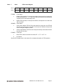
On boards without FIFOs or memory buffers, DMA is required to support high-speed sampling at rates
above the maximum sustainable interrupt rate, which may vary from 1,000 to 20,000 depending on the
CPU and operating system. However, DMM-32X-AT contains a 1024-sample FIFO for A/D data that
allows the interrupt rate to be much slower than the sample rate. The board can support full-speed
sampling at up to 250,000 samples per second without the use of DMA.
DMM-32X-AT User Manual V1.00
Page 10