1
2.1 tracking particles through an accelerator
handle arbitrary changes in the placement of beamline elements. On entering an
element, a particle has a certain phase-space location with respect to the entrance
frame. PTC tracks the particle as it traverses the element, computing the particle’s
phase-space coördinates with respect to the element’s exit frame. Knowing the
relation between the exit frame of the current element and the entrance frame of
the subsequent element, PTC uses the transformations of the dynamical Euclidean
group4 to hand the particle to the next element.
7
4 É. Forest. Locally accurate
dynamical Euclidean
group. Phys. Rev. E, 55
(4):4665–4674, Apr. 1997.
doi: 10.1103/PhysRevE.55.4665
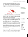
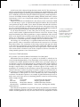
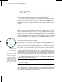
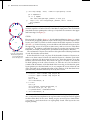
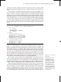
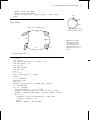
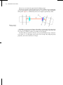
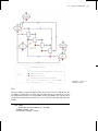
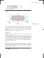
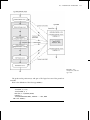
Figure 2.1: LEGO-block
element, with reference
frames for the entrance,
element body, and exit.
The beamline element represented in figure 2.1 is a drift: a block with parallel
entrance and exit faces to which local Cartesian reference frames are attached. The
entrance and exit reference frames have the same unit vectors. The line that links the
two frames has a length L, and it is perpendicular to both those frames. Note that
for the purposes of this discussion, any beamline element (quadrupole, sextupole,
solenoid, etc.) that does not bend the design orbit is a drift.
A LEGO-block element might also be a bend: a block with two faces that have
parallel y-axes (vertical), and x-axes (horizontal) that meet at an angle θ. The two
x-axes and the line joining the two origins form a plane perpendicular to the two
faces. An arc of circle of length L passes perpendicularly through the origin of both
faces. The purpose of this element is to bend an incoming particle trajectory by
approximately angle θ. The internal details of the element—whether it is a sector
bend, a bend with an irregular field, etc.—is, for this discussion, immaterial.
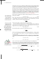
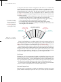
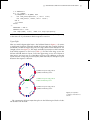
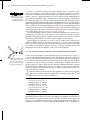
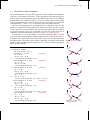
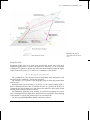
Figure 2.2 illustrates these two fundamental types of LEGO blocks with the
entrance and exit reference frames for their local coördinate systems. The solid
arrows show the direction of the local y-axes and the dashed arrows show the
direction of the local x-axes. In summary, the bend is characterized by a bending
radius ρ, a length L, and two faces, each with a reference frame. The drift is
characterized by a length L and also two faces, each with a reference frame. The
bend is the fundamental block used in the composition of complex blocks; the drift,
of course, is just a special case of the bend.
We are interested in the deterministic motion through each LEGO block, represented by the transformation
zin 7→ zout = f (zin ),
Note that calling the x and
y axes “horizontal” and
“vertical” reflects the bias
of accelerator physicists
towards flat rings with
vertical dipole fields. What
we locally (i.e., within the
element) call the x axis need
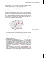
not be horizontal. See, for
example, the discussion of
the vertical bend indicated
in figure 2.5.
D
B
(2.1)
where f denotes a vector of generally nonlinear functions connecting the local
phase-space coördinate zin defined in the entrance frame, to the local phase-space
coördinate zout in the exit frame. The construction of such a transformation depends
on internal considerations that are not needed for an understanding of the LEGOblock approach. The LEGO block for a single element might, in fact, comprise a
Figure 2.2: Two LEGO
blocks: drift (D) and bend
(B).