1
UG-01072
2014.12.15
Channel Input and Output Format
4-15
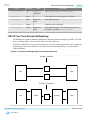
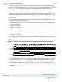
Figure 4-13: Four Channels on Four Wires
valid
channel
data0
data0
data1
data1
0
c0(0)
c0(1)
c0(2)
c0(3)
c0(4)
c0(5)
c0(6)
c0(7)
c1(0)
c1(1)
c1(2)
c1(3)
c1(4)
c1(5)
c1(6)
c1(7)
c2(0)
c2(1)
c2(2)
c2(3)
c2(4)
c2(5)
c2(6)
c2(7)
c3(0)
c3(1)
c3(2)
c3(3)
c3(4)
c3(5)
c3(6)
c3(7)
Channel Input and Output Format
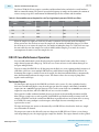
The FIR II IP core requires the inputs and the outputs to be in the same format when the number of input
channel is more than one. The input data to the MegaCore must be arranged horizontally according to the
channels and vertically according to the wires. The outputs should then come out in the same order,
counting along horizontal row first, vertical column second.
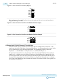
Eight Channels on Three Wires
Figure 4-14: Eight Channels on Three Wires (Input)
clk
xln_v
xln_0
xln_1
xln_2
C0
C1
C2
C3
C4
C5
C6
C7
--
Figure 4-15: Eight Channels on Three Wires (Output)
clk
xOut_v
xOut_0
xOut_1
xOut_2
C0
C1
C2
C3
C4
C5
C6
C7
--
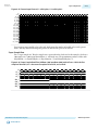
Four Channels on Four Wires
Figure 4-16: Four Channels on Four Wires (Input)
clk
xln_v
xln_0
xln_1
xln_2
xln_3
FIR II IP Core Functional Description
Send Feedback
C0
C1
C2
C3
Altera Corporation