1
Evaluation Module Theory of Operation
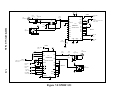
RS-232 Connections and JP1
which will subsequently reset the DSP56007. The MC68705K1 source and object code
are available from the Motorola DSP Division; contact your local Motorola FAE.
3.5
RS-232 CONNECTIONS AND JP1
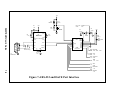
RS-232 is an often-abused standard, and the direction of the signals present on pins 2
and 3 of the DB9 connectordo not always conform to the standard. JP1 provides the
user with the ability to reverse these two pin connections without resorting to NULL
Modem adapters or rewiring cable connectors. As shipped, JP1.1 is connected via
shorting jumpers to JP1.3 and JP1.2 is connected to JP1.4. This connects J4.2 to the
OUTPUT of the Evaluation Module’s RS-232 level converter (U4) and J4.3 to the
INPUT of the board’s RS-232 receiver. These directions can be reversed by reorienting
the shorting jumpers and turning them 90 degrees (one-quarter turn), thereby
connecting JP1.1 to JP1.2 and JP1.3 to JP1.4. The user should never need to rewire an
RS-232 connector in order to establish Evaluation Module communications with a
host computer.
3.6
OPERATING MODES AND SRAM REFRESH IN THE 56007
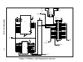
In modes 0, 1, 2, and 3 the SRAM is refreshed from the nvRAM and the DSP can
bootstrap from the SRAM via the EMI if a valid bootstrap mode is used. When in
modes 4, 5, 6, and 7 the SRAM is not refreshed. Refreshes are not affected by jumpers
on the expansion connector, J5. Jumpers J5.37 and J5.39 must be inserted to have full
DSP control of the SRAM and nvRAM after bootstrap.
3.7
EVALUATION MODULE PARTS LIST
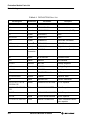
The parts list of the DSP56007EVM is shown in Section 8.
3.8
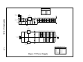
POWER SUPPLIES
The Evaluation Module requires power sources, for both analog and digital circuits,
in order to operate. Bipolar analog power (use a linear power supply for best results)
3-6
56007EVM User’s Guide