1
INST A LL AT ION I NST RUCT IO NS
Before starting the project you should acquire any required planning or other per missions. If you are
installing in or near to an existing building or boundary you should get appropriate professional advice.
You should acquaint yourself w ith the health and safety guidelines that apply to all the equipment and
materials you are using. At all stages these guidelines should be follow ed. Installation of gas-fired plant
should only be undertaken by a Gas Safe registered fitter and all electrical w ork should be carried out by
a suitably qualified technician.
It is far easier to attach the fittings to the pool before it goes into the ground (see sections 7 & 8, below ).
1
Choose the site for your pool. Ideally it should be flat land that gets plenty of sunshine, is not
too close to trees but w hich is also sheltered from the w ind. Avoid underground services
(telephone cables, sew age pipes etc.). There should be space for the plant room, w hich occupies about 2m3 excluding the boiler (if used).
The plant may go in a corner of a nearby garage or shed, or in a purpose-built enclosure.
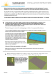
The key to good installation is good compaction of the base and constant checking of levels. A
Sunquest pool holds 60 tonnes of water.
Excavate pool area to required depths (see table
at the end of these instructions for dimensions of
pool shells). Allow an additional 100mm for the
sand bed base. Or appropriate depth if laying a
concrete base - a concrete base may be required
if ground conditions are poor.
Mark out the pool using the dimensions at the
back of this manual, adding 300mm all round the
sides for over-excavation.
Allow only 100mm over -excavation on the depth
(additional 100mm if using insulation).
300mm over-excavation
When the pool arrives on site physically check the dimensions of the pool and adjust the
groundw ork accordingly.
2
Mark the finished pool shell level as a datum on pegs using a w ater pipe, dumpy level or laser
level. Ensure that this is the top of pool shell level not the finished paving level.
If you are installing the pool indoors, start from the desired
finished floor level and measure
dow n, allow ing for floor finish to
get the correct level for the pool
shell.
PG 1/8
V 1.6 (1407)
INST A LL AT ION I NST RUCT IO NS
3
Excavate pool area to required depths (see table at the end of these instructions for dimensions
of pool shells). Allow an additional 100mm for the sand bed base or appropriate depth if laying a
concrete base.
Dimensions show n in mm
4
100mm insulation can be supplied (please ask Sundance Pools for information on the correct
insulation material). If this insulation is to be used the excavation w ill need to be 100mm deeper.
A base construction of Type 1 MOT can be laid w ith sharp sand used to get the base completely
level as required.
The insulation should be placed directly onto the sub-base and the pool shell placed directly on
the insulation.
5
Use flexible land drains (from a builders merchant) and lay them to ter minate in a sump dug
at the edge of the cavity at its low est point. We recommend a 450mm chamber base is used
with appropriate risers to ground level (allow ing for paving etc.). Cap off w ith an inspection
cover.
An electric submersible pump can be
low ered into this chamber to remove any
build-up of groundw ater. In areas w ith high
water table it is advisable to per manently
install a pump—we would alw ays
recommend a pump w ith an internal float
sw itch.
Poor ground conditions may require you to
put the pool on a concrete sub-base w ith
sand laid on top. If in doubt, contact
Sundance Pools.
PG 2/8
V 1.6 (1407)
INST A LL AT ION I NST RUCT IO NS
5
7
Lay a bed of clean sharp sand and compact it using a plate vibrator. For accurate results place
lengths of galvanised pipe at either side of the bottom of the hole and ensure that they are at
the appropriate levels. A length of timber laid edgew ise betw een the pipes can then be used to
level off the sand (see diagram).
Install fittings to pool: underw ater light, return jets,
skimmer, counter current (if applicable) etc. The
light is normally fitted into the deep end w all or
side w all of the pool. Ensure the light is fitted on a
flat surface.
Consider carefully the position of the return jet(s)
and skimmer(s). Pools from the Ceramic Range
have moulded skimmer flanges and skimmers are
therefore in a fixed position. If there is no countercurrent unit to be fitted, the skimmer box should
be fitted at the deep end and the return jets
opposite it at the shallow end. The jets should be
positioned and subsequently adjusted to create
good sw irl in the w ater.
Bear in mind the position of the plant room to
shorten the pipe run. Some pools w ith steps
require the return jets to be positioned on the side
of the pool. Adjust the return jet eyeball so that it
keeps the steps clean.
A skimmer and counter -current will conflict w ith
each other w hich w ill need to be considered.
PG 3/8
V 1.6 (1407)
INST A LL AT ION I NST RUCT IO NS
8
Pay special attention to health and safety guidelines at this stage: it is essential that you use
suitable respiratory protection w hen cutting and abrading fibreglass. Indoors you should ensure
that the area is w ell ventilated. Outdoors you should ensure that co-workers are not dow nw ind of
the cutting operation.
Return jets should be positioned on a flat surface just below the reinforcing rib w here possible.
They require a 60mm circular hole. To fit any equipment to the pool shell, mark out the position of
the unit on inside of pool. Cut out the 60mm holes w ith a hole cutter or jigsaw (w ith a jigsaw
ideally use a tile cutting carborundum blade). Check aperture is the correct size.
Clean off the bitumen paint (non-ceramic pools only) on outer side of pool using a solvent such
as petrol. Smooth fibreglass on outside of pool using a sander or in extreme cases an angle
grinder. Do not remove too much of the thickness of the pool w all. Clean fibreglass again w ith
solvent to remove dust etc. Fit item using seals and silicon etc. as per enclosed instructions.
The skimmer box should be fitted as high up the pool as possible, just under the lip (though the
lip should not be removed). First cut out a section of the reinforcing rib (non-ceramic pools only)
using an angle grinder. This should be w ide enough to accommodate the full w idth of the box. On
larger pools w e recommend cutting the reinforcing rib across the skimmer once the pool is
levelled up and in the hole.
To fit the skimmer hold the faceplate to the inside of the pool and mark the holes at tw o corners
on a diagonal. Drill these out and fix the faceplate using the long bolts and nuts supplied. Drill out
the other holes through the faceplate. Then mark for the rectangular cut-out by draw ing round the
aperture in the faceplate. Remove the faceplate and cut out the rectangle by using a suitable
angle grinder and cutting approx. 4mm outside the mark to allow for the lip on the faceplate.
Smooth off the exterior of the pool and fit skimmer w ith seals and adequate sealant. In order to
bring the lid of the skimmer up to the finished floor level it may be necessary to use some
extension rings available from Sundance Pools.
The skimmer box has tw o holes in the bottom of the cylindrical section. Tw o threaded plugs are
provided, one w ith a cut-out to allow partial flow and one complete. The complete plug should be
screwed into the hole on the pool side of the cylinder and the plug w ith the cut-out should be
discarded, leaving the other hole open to take the pipew ork.
PG 4/8
V 1.6 (1407)
INST A LL AT ION I NST RUCT IO NS
9
Place the pool in position. Check that it is at the correct depth and is level. If more sand has to be
added beneath it, be sure to compact it w ell before returning the pool shell to its position.
Once the pool is level, fill it w ith w ater to a depth of 300mm in the deep end. Check that the pool
has remained level and adjust if necessary. Start caulking under the pool in order to prevent it
moving as it fills. Make a barrier under the curve of the deep end all the w ay round using a stiff
4:1 sand and cement mix (see diagram). Once caulking is complete, check levels once more and
re-commence filling the pool w ith water.
END VIEW
sand cement mix
water depth 300mm
10
Backfilling should be done w ith a dry sand and cement mix at a ratio of approximately 10:1. Avoid
allow ing backfill material to get into the pool.
As the pool fills, backfill to w ithin 300mm of the w ater level. Gently consolidate the sand and cement mixture by foot or w ith water (if using w ater be careful not to w ash all the cement out of the
mixture). Check that pool rim remains in shape: use w ooden supports to the side of the cavity if
needed to stop it bow ing out; if the sides of the pool bulge inw ards remove backfill to relieve them.
Continue backfilling until you reach the level of the pipew ork. Be careful to fill the voids fully beneath steps w ith concrete. Roman ends may need supporting to ensure that they are level.
300mm
sand cement mix
PG 5/8
Note:
for
in-
V 1.6 (1407)
INST A LL AT ION I NST RUCT IO NS
11
Connect the pipework to the fittings by first cleaning the
pipe and fitting surfaces with solvent cleaner and then
applying glue to both surfaces. PTFE tape should be
used on all threaded joints.
Check carefully for leaks (pressure test) as the pipes run
through the backfill and are inaccessible when the pool
is finished. Keep pipe runs horizontal wherever possible.
Continue to backfill to within 150mm of the top edge of
the pool.
Underwater Light (UWL) 12 VOLT
The underwater light should be fitted to the pool shell as
per the manufacturer’s instructions. The light must be
mounted on a flat surface so it may be necessary to mount
it higher than the instructions advise due to the curvature
of the pool. On the outside of the pool, the union and conduit should be fitted to the
light. Use glue and PTFE as necessary. The cable runs inside the conduit and up to
the deck box which should be attached to the top of the conduit. The deck box should
be mounted flush with the paving and is where the 12V supply from the plant room is
connected. The 12V transformer for the light must be mounted in the plant room.
12
Cast a concrete ring around the pool. For outdoor pools allow sufficient slope to the base
so that surface water drains away from the pool (at least 20mm fall away per metre of surround).
For an indoor pool use flat top coping stones and ensure the concrete has a fall towards
the pool so that surface water returns to the pool.
paving slabs
coping stones
(external)
patio
sub-st ructure
pool shell reinforcing rib
(non-ceramic pools only)
concrete ring
pipework
ground
PG 6/8
water line
sand/cement backfill
V 1.6 (1407)
INST A LL AT ION I NST RUCT IO NS
TYPICAL PLANT ROOM & PIPEWORK SCHEMATIC
The below schematic shows a typical plant installation with the addition of solar panels.
PG 7/8
V 1.6 (1407)
INST A LL AT ION I NST RUCT IO NS
Pool (m)
Sunquest 36
Length
Width
A
B
2000mm
11.0m
4.3m
435mm
Bolero
7.5m
3.3m
1500mm
Jetswim
4.0m
2.2m
Jetswim 5m
5.0m
C
D
Weight Perimeter Capacity
Salt
185mm 1020mm
1500Kg
30.6m
60,000l
425Kg
1650mm 1000mm 1020mm
450Kg
20.6m
33,000l
230Kg
500mm
1200mm
500mm 1200mm
250Kg
12.4m
8,200l
60Kg
2.2m
500mm
1200mm
500mm 1200mm
250Kg
14.4m
10,500l
75Kg
10.0m
3.8m
1000mm
1500mm 1500mm 1500mm
980Kg
27.6m
39,600l
275Kg
Aphrodite
9.0m
3.8m
1000mm
1500mm 1500mm 1500mm
880Kg
25.6m
38,200l
260Kg
Aurora
7.5m
3.75m
1000mm
1500mm 1000mm 1500mm
730Kg
22.5m
33,000l
225Kg
Olympia
6.2m
3.3m
1000mm
1500mm 1000mm 1500mm
600Kg
19.0m
23,000l
160Kg
Solaris
5.5m
3.0m
1000mm
1500mm 1000mm 1500mm
530Kg
17.0m
18,000l
125Kg
Pico
4.5m
2.5m
1000mm
1400mm 1000mm 1400mm
430Kg
14.0m
8,200l
60Kg
Apollo
Note. We advise that under no circumstances should the w ater
be em ptied from a pool w ithout referring to Sundance Pools
SUND A NCE POOLS CO NTACT TE LEPHO NE 01 296 7 15 071
PG 8/8
V 1.6 (1407)