1
Exterity SD Receiver Administrator’s Guide
Phono Video Interfaces
Use standard phono cables to output video to televisions/displays as follows:
Composite Video: Connect the Composite output to the Composite input on the television.
Component Video: Connect the Y, Pb and Pr outputs to the similar-marked inputs on the
television.
RGB Video: Connect the Y, Pb and Pr outputs to the television‟s Green, Blue and Red inputs
respectively. Connect the Composite output to the sync input on the television.
SVideo Interface
Use a standard SVideo cable to connect this interface to the SVideo input on the television.
Phono Audio Interfaces
Use standard phono cables to connect left/right analogue audio outputs to the similar-marked
inputs on the television/display.
Serial TV
This RJ45 interface is used to allow the receiver to communicate with a serial-controllable
television. The interface wiring is shown in APPENDIX E. Contact your Exterity supplier for
more details on supported televisions.
IR Out
This interface is used to allow the receiver to control a television using infra-red. If this
functionality is required, contact your Exterity supplier to obtain an IR transmitter.
IR eye
On units with a built-in IR eye, simply point the remote control handset at the eye on the front
of the unit in order to control the receiver.
IR jack
Connect the IR extender cable or tethered remote control to the IR jack to enable the user to
control the receiver using the remote control handset.
Ethernet Ports 1 & 2
The TriplePlay model provides two 10/100 Mbps Ethernet ports to allow other devices (e.g.
PC, IP phone) to be connected to the main network. Devices should be attached to these ports
using a standard straight-through Cat 5 cable.
If the receiver itself is powered using POE, Ethernet 1 provides power over Ethernet (POE) out
up to 6.5W using the 802.3af standard. Ethernet 2 is a standard, non-powered port.
LED
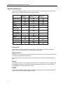
The status LED (blue on idaptor variants and green on iSocket variants) lights when the
receiver is switched on. The LED behaviour is as shown in Table 2.
17