1
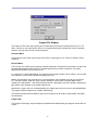
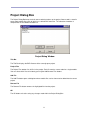
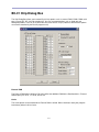
OK Button
The OK Button exits after saving any changes made within the Chip Dialog Box.
Cancel Button
The Cancel Button exits and disregards any changes made within the Chip Dialog Box.
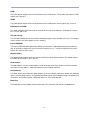
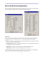
I/O Pin Grid
The I/O Pin Grid allows you to define the initial state of each available I/O pin whenever the processor is
rebooted. Each pin can be set to one of four states -- tristate, pullup, output-high and output-low:
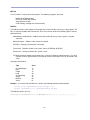
IN Input -- Configures the corresponding pin as a tristate (high impedance) input. Typically 5 V is logic
high (on 5 V systems) and 0 V is logic low.
P Input w/Pullup -- Configures the pin as an input with pullup. This state is typically used to sense the
state of passive devices such as switches.
0 Output Low -- Configures the corresponding pin as a logic low output, which is 0 V.
1 Output High -- Configures the pin as logic high output, which is typically 5 V.
The I/O Pin Grid defines only the initial states of each pin. After startup, you can also have the program
configure each pin independently using procedure PutPin or other system calls.
Known Bugs
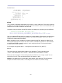
If you enable the cache option, the program will occasionally fail to start after download or reset. A
workaround is to disable this option.
14