1
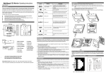
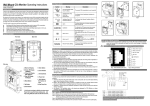
CO2 Transmitter/ Controller Model #: AT-VLB-02-PID-NL-M1 User Manual Specifications Power supply 24VAC (50/60HZ±10%), 24VDC Consumption 1.6 W max. Carbon Dioxide : Non-Dispersive Infrared Detector (NDIR) Gas sensor ABC Logic Self Calibration (default: effective) CO2 measuring range 0~2,000ppm Accuracy@25℃(77℉),2000ppm ±40ppm +3% reading Stability <2% of FS over life of sensor Non linearity <1% of FS Response time <2 minutes for 90% step change Warm up time for each turning-on <5minutes (operational) 0~10VDC(default), other voltage output type selectable by jumper J1 1x analog output Linear or PID output type selectable by jumper J3 See ‘Analog Output Type Selection’ for details Storage conditions -10~70℃(-40~158℉)/0~95%RH, non condensing Operation conditions 0~50℃(32~122℉); 0~95%RH, non condensing Net weight/ Dimensions 110g/102mm×90mm×40mm Installment standard 65mm×65mm(2”×4”) wire box, or hang on a nail Version V. E072 Mounting and Wire Connection Notice the supply power voltage of the monitor: 24VAC. Do not install the monitor on voltages higher than marked on the monitor. Follows the step 1to step 4 in figure1 to remove the cover. Please note use your nails or other unship tools to depress the both clips which are on the sides of the monitor. Mount the monitor on the place where you want to detect CO2 level. Do not mount it near diffuser or any steam source, in direct sunlight. Mount the wall plate first, there are two dimensions available (see figure 2). Place the monitor against the wall at desired location; make sure wires can be passed through the holes on the wall plate. Connect wires to terminal strips, (see figure 3). Make sure wiring connection correct and secure. Follows the step 5 to step 7 in figure 4 to close the cover. Figure.2 wall plate Figure.1 Open it 28.00 3.00 55.00 4.50 100.00 8.00 45.00 1 2 4 3 80.00 28.00 60.00 1 Figure.3 wiring diagram Figure.4 close it F2000TSM-CO2-X-100/101-V jump selection J1J2 J1J2 0-10V 0-20mA 0-5V J1J2 J1J2 2-10V 4-20mA V Line Voltage 1-5V CO2 Common Transformer J1J2 S1S2 1 2 3 24VAC Transformer S1S2 S1 S2 1 1 2 2 3 3 current output voltage output 6 5 1 2 3 7 Output and jumper selection Connection Terminal Function Electrical Data 1 G+ Power(+) 24VAC/24VDC + 2 G0 Power ground (-) 24VAC/24VDC 3 OUT Analog output (+) selectable 0~10VDC = 0~2,000ppm CO2 (default) Analog Output Type Selection Power off and open the front cover. You may see a group of jumpers at the bottom right of the PCB board. First, set jumper S2 and S3 to be voltage output state (both with the 2 nd rd and 3 pin connected). Then select voltage output type via jumper J1: J1 voltage output connection 10VDC disconnection 0~10VDC (default) Then select voltage output type between linear output and PID output via jumper J3: J3 Voltage output type connection Linear output disconnection PID output (default) Use jumper J4 & J5 to select CO2 set point for PID output: J4 J5 CO2 set point for PID output disconnection disconnection 600ppm connection disconnection 800ppm disconnection connection 1000ppm (default) connection connection 1200ppm Important Instructions: 1. Don’t shake or hit the monitor too much in shipment or in mounting to protect the internal infrared CO2 sensor from any damage and excursion of infrared receiver. 2. When First use CO2 monitor, or Reuse CO2 monitor after a long time in stock, Keep the CO2 monitor energized continuously for at least 2 days to let CO2 sensor’s ABC Logic measurement is still incorrect, then let its ABC Logic TM TM self-calibration system operate properly. If it’s Self Calibration System work as follows: During a 14-day period, place the CO2 monitor twice in outdoors or unoccupied places where CO2 level is around 400ppm. Each time let it being there for more than 4 hours. If the CO2 measurement is in its accuracy limit, it indicates the measurement right. Notice: Use of cellular telephones or radio transceivers with two feet of the sensor during calibration process could cause sensor interference, calibration errors and affect sensor accuracy. Please refrain from using these devices during sensor calibration. 2