1
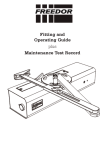
Fitting and
Operating Guide
plus
Maintenance Test Record
Keep this guide in a safe place.
Contents
Introduction and Glossary
Contents of the Box
Prior to Installation
Page
2
3
4
Important Information
5
Door Type and Installation Position
6
Preparing Freedor
7
Installation - Radial Arm Set-up (Pull Side)
8
Installation - Closer Arm Installation (Pull Side)
9
Installation - Radial Arm Set-up (Push Side)
10
Installation - Closer Arm Installation (Push Side)
11
Installation - Mounting Freedor
12
Installation - Additional Functionality
13
Installation - Cover Assembly
14
Installation - Battery Installation
15
Operation and Self-Test
16
Testing Freedor using the Fire Alarm
17
Sensitivity Adjustment
18
Battery Pack Replacement
19
Troubleshooting and FAQs
20
Beeps and Flashes
22
Maintenance Schedule
24
Maintenance Record
25
Commissioning Certificate
26
Manufacturer’s Warranty
27
Manufacturer’s Classification:As required By EN 1154:1997 and EN 1155:1997
ID of Certification Body: 1121
Registered Address:- Fireco Ltd., 30 New Road, BRIGHTON BN1 1BN, UK
Power size: 3
Manufactured in the UK
EN1154:1997 + A1:2002
Tested and found to comply with all the relevant clauses of
those standards harmonised under the CPD
EN1155:1997 + A1:2002
(EU Construction Products Directive)
1
1121
4 8 3 1* 1 3
3 8 3 1* 1 0
Introduction and Glossary
Freedor is a battery operated electrically powered free-swing door closer for fire doors with
Category B signal activation to BS7273-4. It is designed to allow users to hold open a fire
door safely and legally, and it will automatically release upon “hearing” the fire alarm.
It is recommended that a fire door is not held open at an angle of less than 65 degrees.
Glossary of Terms used in this guide.
Set Angle - The position of the radial arm bolt on the radial arm will determine the angle
at which Freedor will enter free-swing mode.
Door closer mode - The default mode for Freedor. No matter what angle Freedor is
opened to, it will close the door.
Free-swing mode - If Freedor is in the free-swing mode, it will act as if there is no door
closer fitted, after it is opened to the set angle.
Fire Alarm mode - Upon detecting the noise of a fire alarm, Freedor will sound ten “HiLo” tones whilst flashing the LED red. Freedor will cause the door to close if it is being held
open and then sound ten “Lo-Hi” tones to indicate closure due to the fire alarm.
Fail-to-Safe mode - If Freedor fails a self-test, it will fail-to-safe and close the door. The
unit will then start to beep and flash its LED in a sequence dependant on the error. During
this mode, the reset button will not be useable and Freedor will not hold the door open until
the error has been cleared.
Reset Button - Depressing the reset button will change the mode that Freedor is currently
in. Holding the reset button for 5 seconds will cause Freedor to perform a soft-reset. This
button will become disabled during fail-to-safe mode and will be temporarily disabled for 5
seconds after use.
LED - Light Emitting Diode. Adjacent to the reset button is a bi-colour LED which
illuminates red or green. The LED flashes to signal the Freedor’s status.
Battery tamper microswitch - Connecting the battery pack and securing the two battery lift screws will depress a tamper switch. If the battery lift is removed during operation,
the tamper switch will change state and Freedor will enter a fail-to-safe mode and close the
door.
PCB (Printed Circuit Board) - The PCB houses all the electronics used to make Freedor
function. It sits above the magnet assembly and has the DIP switches and variable resistor
which sets the unit’s functionality and audio sensitivity respectively.
2
Contents of the Box
Please check that you have all the contents listed below.
The Freedor box contains:
Tools and Equipment Required:
1 x Freedor unit
• Pozidriv No. 2 screwdriver
1 x User Guide
• Flat-blade screwdriver
(no wider than 6mm)
1 x Fitting Template
• Electric drill
1 x Closer Arm Pack
• Drill bits: 3mm diameter
1 x Parallel Arm Bracket
• 11mm socket and ratchet
1 x Battery Pack
• 13mm spanner
1 x Freedor Adhesive Logo
• Stud and cable detector
1 x Radial Arm
• Marker pen
1 x Radial Arm Bolt & Radial Arm Pivot Bag
contains: 1 x Radial Arm Assembly,
1 x Radial Arm Pivot Assembly
• Safety goggles
1 x Freedor Body & Arm Fixtures
contains: 4 x No. 8 Screw, 2 x No. 10 PH
Screw, 4 x No. 10 CSK Screw,
M5 Short PH Screw,
1 x Black Plastic Screwdriver
Wall Mount
Closer Arm
Claw
Radial
Arm Bolt
Radial Arm
Blanking
Plate
Cover
Sensitivity
Adjustment
Hole
Microphone
Hole
Closer Arm
Closer Arm
Screws
Reset Button
LED
Backplate
3
Prior to Installation
Please ensure the following:
1. That a suitable Automatic Fire Detection alarm system is installed;
2. The Fire Alarm system is working correctly, i.e. the sounders work when activated;
3. The fire door closes tightly against the frame whilst checking the fire door is fully
compliant as intended;
4. Freedor is of a suitable power size for the door it is to be installed on;
5. The door, the door frame and surrounding fixing points are checked for potential
interferences or danger, such as electrical wiring;
6. The fire door is suitable for Freedor installation. In a power size 4 installation,
Freedor is suitable for fire doors up to 1100mm wide and 80kg;
7. An internal stop should be installed to prevent Freedor being opened past its maximum
opening angle; i.e. 105 degrees when installed on the pull side and 135 degrees when
installed on the push side. The stop must be of a standard design and correctly fixed;
8. Freedor should be included in the Fire Risk Assessment (as required by the Fire
Precautions [Workplace] Regulations 1997, also required by the Regulatory Reform (Fire
Safety) Order 2006);
9. When Freedor is holding a fire door open, the Freedor “listens” continually for the sound
of a fire alarm. When the alarm sounds, Freedor will verify the alarm over a 20 second
period and then cause the fire door to close.
4
Important Information
Freedor must only be used for the purpose for
which it is designed. It is not suitable for
external use. Read this guide and follow the
instructions carefully. Keep this guide in a safe
place e.g. in the Fire Risk Assessment file for future reference.
Freedor, when installed correctly, complies with
BS 7273-4 Category B.
Supplementary information about the sound
generated by a fire alarm: The British Standard
for fire alarm installation, BS 5839-1: 2002,
(Clause 16.2), states:
The sound pressure level of alarm signals
should be generally, throughout all
accessible areas of the building not less
than 65dB (A) ... where the sound pressure
level of background noise is greater than
60dB (A), the sound pressure level of the
fire alarm signal should be 5dB above the
sound pressure level of the background
noise.
Power Supply
Rated Voltage: 9.82V
Power Consumption (at rated voltage): 0.05W
Protection: Resettable solid state fuse
Freedor constantly checks the voltage of the
connected battery pack and will fail-to-safe on
detecting the voltage reaching a low level.
Freedor will not start-up if a low voltage
condition is detected.
Only connect new battery packs supplied by
Fireco Ltd. or by approved suppliers of Freedor.
Failure to do so and the use of unauthorised
battery packs could result in damage to the
product and cause it to become unsafe.
5
Door Type and Installation Position
Freedor can be installed in one of four positions; clockwise or anti-clockwise opening doors,
and on the pull side or push side of the door. Using the diagram below, determine where
you wish Freedor to be installed.
Clockwise Opening Door
Pull Side
Anti-clockwise Opening Door
Push Side
Push Side
Pull Side
During the installation process, the method for installing Freedor will differ depending on
which side of the door it is to be installed. If the title of the installation section of this guide
mentions a specific side, make sure it is the correct side for the installation. This rule also
applies to various steps which will present a “pull” and “push” side option. If the
installation section does not mention a specific side, it is correct to follow for either
installation type.
6
Preparing Freedor
Freedor requires minor dis-assembly to prepare it for
installation upon the door. Follow the instructions detailed
below to prepare Freedor for installation.
1. Remove the Freedor body from under the top tier of
packaging.
2. Unscrew the 2 screws holding down the blanking plate
and lift it away.
3. Unscrew the 2 screws holding the battery lift and slide it
gently away from the cover.
4. Gently push the battery lift legs toward each other so that
they can clear the cover and remove the battery lift.
5. Once the 4 holding screws are removed from the cover (2
from the blanking plate, 2 from the battery lift), the cover
can be removed.
The instructions for the Radial Arm Set-up and Closer
Arm Installation are set out on separate pages for
pull and push side installation. Ensure that the
instructions for the required configuration are
followed.
7
Installation - Radial Arm Set-up (Pull Side)
Pull side installation only - for push side instructions,
see page 10.
1. Remove the radial arm and the radial arm bolt assembly
from the packaging. The radial arm bolt assembly contains:
1 x M8 Bolt, 1 x Metal Sleeve and 1 x M8 Nyloc Nut.
2. Using the diagrams below, select the angle at which the
door will enter free-swing mode and insert the bolt through
the slot in the radial arm at the correct position. The
diagrams show the minimum, maximum and right-angle
installation points for the radial arm bolt; the bolt can be
installed at any position between the minimum and
maximum points.
3. Assemble the radial arm bolt by sliding the sleeve and
the nyloc nut onto the bolt. Tighten down the nut to
fasten the bolt to the radial arm.
Clockwise Opening
TOP
TOP
65 degree set angle
90 degree set angle
(min.)
Anti-clockwise Opening
TOP
105 degree set angle
(max.)
TOP
TOP
TOP
65 degree set angle
(min.)
90 degree set angle
105 degree set angle
(max.)
8
Installation - Closer Arm Installation (Pull Side)
Pull side installation only - for push side instructions,
see page 10.
1. Place the radial arm and radial arm bolt assembly on
the square pinion of the closer so that the radial arm nib
sits at right angles to the backplate.
2. Take the largest metal washer from the door closer arm
pivot pack and place it on the central recess of the radial
arm.
3. Push the nylon shoulder washer into the door closer arm
from the flat bottom side. Place the door closer arm on top
of the radial arm, ensuring the door closer arm sits
between the Freedor PCB and the radial arm bolt.
4. Place the nylon washer and metal washer into the door
closer arm (in that order). Tighten the door closer arm to
the closer body using the door closer bolt. Tighten the
bolt until the arm is secure ensuring it is not over
tightened. Check that the arm can move with little
resistance, loosen the bolt if necessary.
Note. The two diagrams below are examples of
how the backplate assembly should look at this stage.
Installation instructions continue on page 12.
Clockwise Opening
Anti-clockwise Opening
9
Installation - Radial Arm Set-up (Push Side)
Push side installation only - for pull side instructions,
see page 8.
1. Remove the radial arm and the radial arm bolt assembly
from the packaging. The radial arm bolt assembly contains:
1 x M8 Bolt, 1 x Metal Sleeve and 1 x M8 Nyloc Nut.
2. Using the diagrams below, select the angle at which the
door will enter free-swing mode and insert the bolt through
the slot in the radial arm at the correct position. The
diagrams show the minimum, maximum and right-angle
installation points for the radial arm bolt; the bolt can be
installed at any position between the minimum and
maximum points.
3. Assemble the radial arm bolt by sliding the sleeve and
the nyloc nut onto the bolt. Tighten down the nut to
fasten the bolt to the radial arm.
Clockwise Opening
TOP
TOP
85 degree set angle
90 degree set angle
(min.)
Anti-clockwise Opening
TOP
95 degree set angle
(max.)
TOP
TOP
TOP
85 degree set angle
(min.)
90 degree set angle
95 degree set angle
(max.)
10
Installation - Closer Arm Installation (Push Side)
Push side installation only - for pull side instructions,
see page 8.
1. Place the radial arm with the newly fitted radial arm bolt on
the square pinion of the closer so that the radial arm nib
sits at a 45 degree angle to the backplate, facing toward
where the hinge will sit.
2. Take the largest metal washer from the door closer arm
pivot pack and place it on the central recess of the radial
arm.
3. Push the nylon shoulder washer into the door closer arm
from the flat bottom side. Place the door closer arm atop
the radial arm, ensuring the door closer arm sits between
the backplate and the radial arm bolt.
4. Place the nylon washer and metal washer into the door
closer arm (in that order). Tighten the door closer arm to
the closer body using the door closer bolt. Tighten the
bolt until the arm is secure ensuring it is not over
tightened. Check that the arm can move with little
resistance, loosen the bolt if necessary.
Note. The two diagrams below are examples of
how the backplate assembly should look at this stage.
Clockwise Opening
Anti-clockwise Opening
11
Installation - Mounting Freedor
Pull Side
1. Place the fitting template against the door with the
required orientation facing you (template A for pull side
installation and template B for push side installation).
2. Fold the template along the upper fold line and hold it
on the door, following the instructions for correct
placement.
Push Side
3. Mark through the template in the desired locations for the
Freedor body and wall mount closer arm fixtures. Drill
pilot holes using a 3mm drill bit fitted in an electric drill.
4. Screw a Freedor fitting screw into each of the 4 pilot holes
made in the door. Leave a gap of approximately 5mm
under the screw head.
5. Unscrew the two hexagonal head screws connecting the
two closer arm parts together.
6.A. Pull Side Installation. Using the two closer arm fitting
screws, affix the wall mount closer arm to the door frame
following the template for correct orientation.
OR
6.B. Push Side Installation. Take the wall mount closer
arm and affix this to the parallel arm bracket using the
short screws included in the same pack as the bracket
fitting screws. Using the four parallel arm bracket
screws, affix the parallel arm bracket to the underside of
the door frame.
7. Hang the backplate assembly on the door using the 4
screws fitted in step 4. Secure Freedor to the door by
tightening the 4 screws fully.
8. Locate the 2 claw springs connected between the claw
and the backplate. Cut the lowest claw spring in two,
allowing the upper most spring to pull the claw upwards.
9. Loop the battery input wiring over the closer so it is
accessible from beneath the closer.
12
Installation - Additional Functionality (inc. Automatic Free-swing)
The factory default setting for DIP switches 1, 2 & 4 is
OFF, DIP switch 3 is set to ON and should only be
turned OFF if Automatic Free-swing is to be disabled,
see below for details. Freedor will only change modes if
prompted to do so by the user or a fire alarm or fault is
detected.
Freedor can perform night-time releases, automatically enter
free-swing mode or perform a weekly self-test by setting the
appropriate DIP switch.
When adjusting the DIP switches, ensure the supplied black
screwdriver is used to avoid damage being caused to the
PCB by static discharge.
DIP Release Reset
Switch Time Time Night-time Release - DIP switches 1 & 2
1
20:00 8:00 This function will place Freedor into door closer mode and it
2
21:00
7:00
1 and 2 22:00
6:00
will not enter free-swing mode until the reset time is reached.
Whenever Freedor starts-up or performs a soft-reset, it will
assume the time is 12:00 noon. The times stated in the table
to the left are correct if Freedor starts-up at 12:00 noon.
Using the night-time release table on the left, choose the
time span for Freedor to enter night-time release. With the
black plastic screwdriver supplied, push the DIP switches
toward the PCB for the time range selected
Automatic Free-swing - DIP switch 3
DIP Switch
3 ON
4 ON
Self-Test
Tones
Automatic
Free-swing
ON
Weekly
Self-test
ON
If Freedor closes the door due to either the detection of a fire
alarm, a night time release or a self test, then by default
Freedor will revert to Free-swing mode 30 seconds after the
door closes. For night time release this will be when the reset
time is reached. The door then only has to be re-opened
beyond the set angle to hold it open. Turning DIP switch 3 to
OFF disables Automatic Free swing mode and Freedor
operates in door closer mode, requiring the reset button to be
pressed after the door closes.
Weekly Self-Test - DIP switch 4
If Freedor is to perform a weekly self-test, set DIP switch 4 to
ON. 6½ days after start-up, Freedor will perform a self-test; it
will then perform a self-test every 7 days at the same time. If
the door is being held open during a self-test, it will be
released and require resetting by either the reset button, or
will automatically reset if DIP switch 3 is ON.
13
Installation - Closer Speed Adjustment and Cover Assembly
Pull Side
1.A. Pull Side Installation. Slide the door closer arm
around the wall mount closer arm and pull the door
closer arm so that the wall mount closer arm is at a right
angle to the door. Secure the arm in this position using
the two closer screws.
OR
1.B. Push Side Installation. Slide the door closer arm
around the wall mount closer arm and pull the door
closer arm so that the wall mount closer arm is parallel to
the door. Secure the arm in this position using the
two closer screws.
Push Side
2. Freedor will now act as a door closer, allowing the
adjustment of the closing and latching speeds of the closer.
To increase the closing rate of either the closing or latching
speed, loosen the appropriate regulator bolt; to slow the
rate, tighten the regulator bolt. The regulator bolts are
located on the closer. The closing speed is governed by
the bolt labelled 1 and the latching speed is governed by
the bolt labelled 2.
3. Slide the cover over the Freedor body ensuring that the
cover is orientated such that the microphone and the
sensitivity adjustment holes are over the PCB.
4. Place the Freedor logo sticker on the cover indent and
place the plastic pinion cover over the closer
pinion.
5. Place the blanking plate on top of the cover and secure it
with the fixtures removed during the installation
preparation.
6. Similar to the removal of the battery lift during the Freedor
installation preparation, gently push the battery lift legs
towards each other so the battery lift is able to be slid into
its original position. Do not secure the battery lift.
14
Installation - Battery Installation
1. With the Freedor fully assembled and closing the door
correctly, take the battery pack from the Freedor packaging
and record the installation date on the label fitted on the
battery pack.
2. Connect the battery pack to the Freedor’s battery pack
connector that should be protruding from the bottom of
the cover.
3. With the battery pack connected, place it on the battery
lift. Push the battery lift up into the Freedor unit. Secure
the battery lift with the screws removed during the
installation preparation.
4. Once the battery lift is secured and the battery pack is
connected, hold the reset button on the side of Freedor
down until a continuous tone is heard. At this point
release the button and the Freedor start sequence will
commence.
5. When Freedor is powered up it will assume the time is
12:00 noon.
15
Operation and Self-Test
Freedor will operate in one of two modes after installation:
either door closer mode, acting as a typical door closer; or
free-swing mode.
Operation of Freedor differs, dependent on whether automatic free-swing is on (DIP switch 3 ON) or off (DIP switch 3
OFF).
Automatic Free-swing ON - DIP switch 3 ON
1. A few seconds after Freedor is powered up, Freedor will
enter free-swing mode. Open the door past the set angle
and Freedor will hold the door open.
2. If Freedor releases the door due to a fire alarm or self-test,
it will reset to free-swing mode 30 seconds after the door
is closed. If the fire alarm is still sounding, Freedor will
continue to cycle from free-swing to door closer mode. It is
important to note that Freedor will not hold the door open
in free-swing mode until it is opened past the set angle.
3. In the event of night-time release, Freedor will close the
door and re-enter free-swing mode automatically when the
reset time is reached.
Automatic Free-swing OFF - DIP switch 3 OFF
1. After Freedor is powered up, press the reset button.
Freedor will enter free-swing mode. Open the door past
the set angle and Freedor will hold the door open.
2. If Freedor releases the door due to a fire alarm or self-test,
it will require the reset button to be pressed to set the unit
back into free-swing mode. It is important to note that
Freedor will not hold the door open in free-swing mode
until it is opened past the set angle.
3. In the event of night-time release, Freedor will close the
door and give a warning tone (LoLoHiHi) if the reset button
is pressed. Once the reset time is reached, the reset
button will become active again, allowing the user to set
Freedor into free-swing mode again.
16
Testing Freedor using the Fire Alarm
1. Set Freedor to free-swing mode, open the door past the set
angle and allow Freedor to engage.
2. Sound the fire alarm until Freedor causes the door to close.
3. The LED on the side of Freedor should flash every 2
seconds to indicate it is “hearing” the sound of the fire
alarm.
4. Freedor should release the fire door in under 20 seconds.
5. When Freedor is ready to release the door, it will sound a
“high-low” warning tone, repeated a total of 10 times
before releasing the door.
6. After Freedor has released the fire door (and the fire alarm
has ceased) it can be reset after 10 seconds.
Note. If Freedor fails to react to the sound of the fire
alarm, the sensitivity of the unit will need to be
adjusted (see Sensitivity Adjustment).
Alterations to the premises i.e. new furniture, new
carpets etc., might alter the audibility of the fire
alarm. Following alterations, a fire alarm test must
be carried out to ensure that Freedor responds.
17
Sensitivity Adjustment
Each environment will vary and Freedor may need adjusting
to suit individual conditions.
When making a necessary adjustment use the black plastic
screwdriver supplied. Take care not to over adjust as this will
render the unit inoperative.
Adjusting sensitivity if Freedor is not sensitive
enough, i.e. does not respond to the fire alarm:
Acoustic Sensitivity
Minimum Release Level
1. Carefully insert the black plastic screwdriver into the
aperture on the front of the unit, next to the 7 holes for the
microphone.
2. Turn clockwise through no more than 5 degrees (a small
angular adjustment corresponds to a large alteration in
sensitivity).
3. Test Freedor’s response to the fire alarm.
60dB 4. If problems persist repeat steps 1-3.
80dB
Note. The adjustment screw is limited in both directions, once there is a resistance against turning - stop
to avoid damaging the unit.
If Freedor is too sensitive (responds to no apparent sound) follow steps 1-4, but turn anti-clockwise in Step 2.
Note. When turned completely clockwise, Freedor
needs to detect approximately 60dB to register a fire
alarm. When turned completely anti-clockwise,
Freedor needs to detect approximately 80dB to
register a fire alarm.
18
Battery Pack Replacement
When the product determines that a battery low level has
been reached (approximately 24 months), Freedor will fail-tosafe and will not allow the door to enter free-swing mode. If
Freedor is sounding a “Hi-Lo Hi-Lo” tone once every 32 seconds, the battery pack will need replacing.
1. Unscrew the 2 screws securing the battery lift and let it
gently drop down to expose the battery pack.
2. Remove the battery pack from the unit and disconnect the
battery pack connector.
3. Record the installation date on the label fitted to the
battery pack.
4. Connect the new battery pack and place it on the battery
lift. Push the battery lift up into the Freedor unit.
Re-secure the battery lift with the 2 screws.
5. Press the reset button on the side of Freedor until a
continuous tone is heard. At this point release the button
and the Freedor start sequence will commence.
Note. Battery levels are checked once every 30
seconds in all modes.
19
Troubleshooting and FAQs
1. Why is Freedor not releasing when the Fire Alarm sounds?
• Check fire alarm sounds for at least 30 seconds.
• Check fire door is free to close unhindered.
• Check the fire alarm exceeds than 65 dB at the place where the Freedor is fitted.
• Adjust the sensitivity of the Freedor unit (see Sensitivity Adjustment).
2. Why does Freedor release if the fire alarm is not sounding?
• As a safety feature, Freedor has to release to any sound that it “hears” as being
continuous and above 65 dB as this sound could potentially mask the sound of
a fire alarm.
• Check night-time release settings.
• Adjust the sensitivity of the Freedor unit (see Sensitivity Adjustment).
• Check battery pack, is the unit beeping?
3. Why does Freedor not retain the door in an open position after the door has
been opened past the set angle?
• Ensure Freedor is in free-swing mode. Press the reset button and a tone (HiLo) should
sound.
• Is a tone (LoLoHiHi) produced every time the reset button is pressed? If so, Freedor is
currently in night-time release mode and will not become active again until the reset
time is reached.
• Is automatic free-swing mode turned on (DIP switch 3 ON)? If so, wait 30 seconds after a
fire alarm/self-test and Freedor will reset to free-swing mode.
• Check that the battery lift is closed (secured up to the cover) and the battery pack is
correctly installed.
20
Troubleshooting and FAQs continued
4. How can I reset the Freedor without re-installing the battery pack?
• Holding the push button down for 9 seconds in any mode will cause Freedor to perform a
soft-reset. A soft-reset will have the same effect as re-installing the battery pack, unless
Freedor has failed-to-safe. In the event of a failure or tones are heard from Freedor, refer
to the Beeps and Flashes section for more information.
5. How do I change the night-time release, self-test settings or closing/latching
speed once Freedor has been installed?
• The cover needs to be removed to access the closer and DIP switches. To remove the
cover, follow the instructions found in the Preparing Freedor section. Freedor does not
need to be removed from the door to change the closer speed or DIP switch settings.
6. Why is Freedor producing tones and flashing its LED?
• See Beeps and Flashes section for information relating to each sequence.
21
Beeps and Flashes
Beep/Flash Sequence
What it means?
Remedy
Long Lo Tone
Indicates start of power up
test.
No action required.
Lo - Lo - Lo
No DIP switches have been
selected
No action required.
Hi - Lo - Lo
DIP switch 1 has been
selected.
No action required.
Lo - Hi - Lo
DIP switch 2 has been
selected
No action required.
Hi - Hi - Lo
DIP switches 1 and 2 have
been selected
No action required.
Lo - Mid - Hi
Successful self-test
During Power up
During standard operation
Key: * LED flash GREEN
O LED flash RED
*---(32secs)---*---(32secs)---*---(32secs)---*---etc.
LED indicates that Freedor
is working properly.
No action required.
Hi Lo
*
Freedor is preparing to
change modes.
No action required.
HiLo – HiLo – HiLo – HiLo – HiLo – HiLo – HiLo – HiLo
O-------O-------O-------O-------O-------O-------O-------O
HiLo – HiLo
O-------O
Freedor is preparing to
release the door due to a
fire alarm
No action required.
LoHi – LoHi – LoHi – LoHi – LoHi – LoHi – LoHi – LoHi
O-------O-------O-------O-------O-------O-------O-------O
– LoHi – LoHi
O-------O
Freedor is resetting after
releasing the door due to a
fire alarm.
No action required.
and
HiLo – HiLo – HiLo – HiLo
*--------*--------*--------*
22
Beeps and Flashes continued
Beep/Flash Sequence
Error Modes
What it means?
Remedy
Battery tamper switch not
depressed. This will
occur during power up
but will stop when the
battery lift is secured
1. Unfasten the battery lift
2. Disconnect the battery pack
4. Wait 10 seconds
3. Connect the battery pack
and secure the battery lift
4. Hold down the reset button
to power up Freedor
Key: * LED flash GREEN
O LED flash RED
Lo – (2secs) – Lo – (2secs) – Lo – (2secs) – etc.
O----------------O----------------O----------------etc.
After each mode change there
is a 5 second period where the
reset button is unusable. Wait 5
seconds and try again.
LoLoHiHi
HiHiHiHiLoLoLoLo---(4secs)--HiHiHiHiLoLoLoLo---(4secs)--- etc.
HiLo-------(17 minutes)-- etc.
HiLoHiLo------(32 secs)--etc.
Reset Button is currently
unusable
If Freedor has entered fail-safe
mode due to night-time release,
Freedor will be unusable until
the night-time reset time is
reached.
Indicates possible
latching fault
1. Open the door past the set
angle and check if the door is
being held open or not.
2. Press and hold the reset
button until a soft reset
occurs (10 seconds).
3. Ensure no foreign bodies,
such as wires, debris, etc.
are interfering with the
device.
4. Replace the battery pack and
repeat steps 1-3.
5. Contact Freedor Technical
advice line if Freedor holds
open the door.
Low battery mode.
Battery levels are getting close
to critical levels. Freedor will
function normally until critical
battery levels are reached.
Critical battery mode.
Battery levels have reached a
critical level and Freedor has
failed-to-safe. Replace battery
pack.
23
Maintenance Schedule
Preventative maintenance and regular testing will ensure that Freedor functions correctly
at all times. Keep the Maintenance Record up to date.
Weekly
Check Freedor is in the free-swing mode, open the door beyond the set angle and allow it
to settle back. Sound the fire alarm, before the alarm has sounded for 30 seconds the door
should be released and close. If the door is not released, refer to the troubleshooting
section.
Monthly
Carry out the weekly test and in addition clean the unit checking that the 7 holes for the
microphone aperture are open and clear of any dust, dirt etc. Freedor can be cleaned with a
slightly damp cloth.
6 Monthly
Carry out the weekly and monthly schedule and in addition, check:
1. The Freedor unit for signs of wear;
2. The Freedor unit is firmly attached to the door, along with any arm attachments.
Yearly
Carry out the 6 monthly schedule and if possible, check the battery voltage.
Bi-Yearly
Replace battery pack.
Note and Warning
• The unit is designed to detect low battery power or possible faults, it will give a continual
warning (sound a series of beeps) and will fail to safe (no longer operate as a hold open
device).
24
Maintenance Record
The log sheet below is designed to cover a 12 month period and should be filled out after each
alarm test. This log is a formal record of the test and maintenance schedule carried out by a
competent (responsible) person(s) throughout the history of the installation of the Freedor unit.
Serial Number:
Location:
Serial Number is on the back of the Freedor unit.
Installation Date:
Week Result
Installed by:
Date
Sign
Week Result
1
2
3
4
5
6
7
8
9
10
11
12
13
14
15
16
17
18
19
20
21
22
23
24
25
26
27
28
29
30
31
32
33
34
35
36
37
38
39
40
41
42
43
44
45
46
47
48
49
50
51
52
25
Date
Sign
Commissioning Certificate
Certificate of commissioning for the electrically powered hold-open device(s) (please delete as
appropriate) at: Address:........................................................................................................................
..................................................................................................................................................................
..................................................................................................................................................................
I/we being person(s) responsible (as indicated by my/our signatures below) for the
commissioning of the above, particulars of which are set out below, CERTIFY that the
equipment and release arrangements I/we have commissioned complies to the best of my/our
knowledge and belief with the recommendations of BS 7273-4:2007 for the category of
actuation described below, except for the variations, if any, stated in this certificate.
Name (in block letters):.............................................................Position:...............................................
Signature:...................................................................................Date:.....................................................
For and on behalf of:................................................................................................................................
Address:...................................................................................................................................................
..................................................................................................................................................................
............................................................................................Postcode:......................................................
The extent of liability of the signatory is limited to the equipment and arrangements described
below.
O Category B (acoustically activated Freedor)
Variations for the recommendations of BS 7273-4 (Clause 7).............................................................
..................................................................................................................................................................
..................................................................................................................................................................
Brief description of release mechanisms, method(s) of actuation (see 7273-4:2007, Clause 8)
and system design (see BS 7273-4:2007, Clause 10)............................................................................
..................................................................................................................................................................
..................................................................................................................................................................
O All equipment operates correctly.
O Installation work is, as far as can reasonably be ascertained, of acceptable standard.
O I/we have carried out commissioning in accordance with recommendations of
BS 7273-4:2007, 21.5
O Suitability documentation has been completed before/after (delete as applicable) release
mechanisms become operational......................................................................................................
..................................................................................................................................................................
..................................................................................................................................................................
..................................................................................................................................................................
Maintenance: it is strongly recommended that, after completion, Freedor is maintained in
accordance with BS 7273-4:2007, Clause 22.
User Responsibilities: the user should appoint a responsible person to supervise routine testing
of release mechanisms in accordance with BS 7273-4:2007, 22.1 and to supervise all matters
pertaining to the associated fire detection and fire alarm system in accordance with
BS 5839-1:2002, section 7.
26
Manufacturer’s Warranty
Fireco Limited (“we” and “us”) warrants to the customer (“you” and “your”) that the product
will be free from defects in material and workmanship for a period of 24 months from the date
of purchase. If the product is defective whilst under warranty we will, at our option, repair the
product or replace it free of charge.
If the product appears to develop a defect while under warranty please first check that the
product is being correctly used in accordance with this Fitting and Operating Guide and that
the battery packs are functioning. If this does not resolve the problem, please contact us via
e-mail or telephone the Freedor Technical Advice line below.
The warranty does not apply to any defect in the product arising from fair wear and tear, wilful
damage, accident, negligence by you or any third party, abnormal working conditions, failure
to follow the instructions in this guide, misuse or alteration or repair of the product without our
prior approval. The warranty does not cover the battery pack which might need to be replaced
within the period of the warranty. We will not be liable to you for any loss of profits,
administrative inconvenience or indirect or consequential loss or damage arising out of any
defect in the product.
Where the products are sold under a consumer transaction (as defined by the UK Consumer
Transactions (Restrictions on Statements) Order 1976) your statutory rights are not affected by
the terms of this warranty.
Version 1.5
For Technical Assistance contact the UK Technical Advice line on:
0845 241 7575 (Local Rate) or +44 (0) 1273 320 688
e-mail us at help@firecoltd.com
www.firecoltd.com
For all other queries please contact your supplier.