1
Advanced air conditioning systems
WS Series
7.4 Unit Location and Installation
•
•
•
•
•
Install the unit in a location with convenient access to the service panels, air filter and
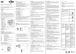
control box. See Fig. 7-2 for minimum permissible distances to adjacent structures.
Protect the unit from any heat source.
Make sure that the unit is level.
For all models, hanging installation is commonly used. Installing the unit resting on a
rigid surface is allowed.
Carefully plan the drainage hose path at a minimum slope of 2%, avoiding sharp
bends or water traps.
Fig. 7-2
7.4.1 Installing the Unit Directly On the Ceiling (Fig. 7-1)
•
•
•
•
•
•
Select the installation location according to the above mentioned considerations and
guidelines.
Mark 4 holes on the ceiling, according to the unit's mounting bracket holes (10).
Drill adequate holes and fix the long ceiling anchors (11) in position.
Lift up the unit onto the hanger anchors through the mounting brackets. Insert four
rubber shock absorbers on the four anchors, as shown in Fig. 7-1. Lock the assembly
with the lock nut.
Should the unit be installed on a rigid surface, stick four rubber absorbtion cushions
on the four corners of the base.
In any mode of installation it is recommended to place under the unit an acoustic
insulation sheet (9).
7.5 Connecting the Water Piping
•
•
•
Clearly identify the water supply piping.
An external safeguard device shall be connected to the water source to limit its output
pressure (in excess of atmospheric pressure) to 6 bar.
Use flexible hoses (4) to connect the water piping according to Fig. 7-3. For piping
size see technical data tables. Use only premium quality flexible hoses and make sure
it withstands the system water pressure. (Note: Ample pressure hoses must be installed
in tall buildings.)
- 19 -