1
1.
BURNER DESCRIPTION
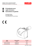
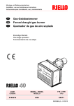
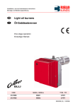
One stage light oil burner.
Fig. 1
2
11
9
1
10
12
4
7
3
5
8
6
D7295
1 – Control-box
7 – Light oil pump
2 – Reset button with lockout lamp
8 – Flue gases slotted holes
3 – Air regulation unit
9 – Heater connection fixing nut
4 – Motor
10 – Air intake grid
5 – Flame tube
11 – Slot regulation screw
6 – Flange with insulating gasket
12 – Capacitor
1.1 EQUIPMENT
Flange with insulating gasket . . . . . . . . No. 1
Screws and nuts for flange to be fixed to boiler . No. 4
Screw and nuts for flange . . . . . . . . . . No. 1
Flexible oil pipes with nipples . . . . . . . . . . . . . . . No. 2
Grommet . . . . . . . . . . . . . . . . . . . . . . . No. 1
7 pin plug . . . . . . . . . . . . . . . . . . . . . . . . . . . . . . No. 1
Flame tube . . . . . . . . . . . . . . . . . . . . . No. 1
1.2
ACCESSORIES
DIAGNOSTIC SOFTWARE KIT
A special kit is available that detects the life of the burner through optical connections with a PC showing
the duty hours, number and types of lockout, control box serial number etc...
Do the following to display the diagnostic:
³
Connect the kit supplied separately to the appropriate socket on the control box.
The information is read after the software program in the kit is booted.
REMOTE RESET KIT
The burner is fitted with a remote reset kit (RS) consisting of a connection to which a button can be connected up to a distance of 20 meters.
For the installation, remove the protection block installed in the factory and install the block that is supplied
with the burner (see wiring diagram on page 7).
3230
2
GB