1
1902 (Eng) (’97. 7. 29)
OPERATING INSTRUCTIONS
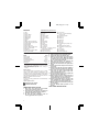
Removing or installing planer blades
Important:
• Always be sure that machine is switched off and
unplugged before removing or installing the blade.
• Use the following planer blades.
Part Nos. 793004-6 793007-0 793322-2
*P-04226 *P-04282
Blades with * mark are available in European countries only. Consult your dealer or the Makita Service
Center when purchasing blades.
For machine with standard planer blades
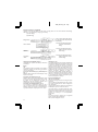
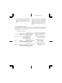
(Fig. 1, 2 & 3)
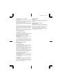
To remove the blades on the drum, unscrew the three
installation bolts with the socket wrench. The drum
cover comes off together with the blades.
To install the blades, first clean out all chips or foreign
matter adhering to the drum or blades. Use blades of
the same dimensions and weight, or drum
oscillation/vibration will result, causing poor planing
action and, eventually, machine breakdown.
Place the blade on the gauge base so that the blade
edge is perfectly flush with the inside edge of the
gauge plate. Place the adjust plate on the blade, then
simply press in the heel of the adjust plate flush with
the back side of the gauge base and tighten two
screws on the adjust plate. Now slip the heel of the
adjust plate into the drum groove, then fit the drum
cover on it. Tighten the three installation bolts evenly
and alternately with the socket wrench.
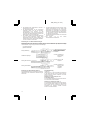
For machine with mini planer blades (Fig. 1, 4 & 5)
1. Remove the existing blade, if the machine has
been in use, carefully clean the drum surfaces and
the drum cover. To remove the blades on the
drum, unscrew the three installation bolts with the
socket wrench. The drum cover comes off
together with the blades.
2. To install the blades, loosely attach the adjust
plate to the set plate with the pan head screws
and set the mini planer blade on the gauge base
so that the cutting edge of the blade is perfectly
flush with the inside flank of the gauge plate.
3. Set the adjust plate/set plate on the gauge base
so that the planer blade locating lugs on the set
plate rest in the mini planer blade groove, then
press in the heel of the adjust plate flush with the
back side of the gauge base and tighten the pan
head screws.
4. It is important that the blade sits flush with the
inside flank of the gauge plate, the planer blade
locating lugs sit in the blade groove and the heel
of the adjust plate is flush with the back side of the
gauge base. Check this alignment carefully to
ensure uniform cutting.
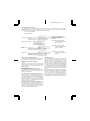
5. Slip the heel of the adjust plate into the groove of
the drum.
6. Set the drum cover over the adjust plate/set plate
and screw in the three hex flange head bolts so
that a gap exists between the drum and the set
plate to slide the mini planer blade into position.
The blade will be positioned by the planer blade
locating lugs on the set plate.
7. The blade’s lengthwise adjustment will need to be
manually positioned so that the blade ends are
clear and equidistant from the housing on one
side and the metal bracket on the other.
8. Tighten the three hex flange head bolts (with the
socket wrench provided) and hand rotate the
drum to check clearances between the blade ends
and the machine body.
9. Check the three hex flange head bolts for final
tightness.
10. Repeat procedures 1 – 9 for other blade.
7