1
SAVE THESE INSTRUCTIONS FOR FUTURE REFERENCE
CONTENTS
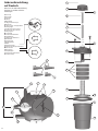
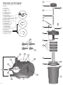
Before you begin, please check that the following items are included in the box:
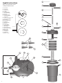
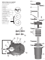
• Pressure-Flo Filter
• UV-C Lamp, installed
• 3 Foam Filters (PF 1000/PF 3000 UVC), 4 Foam Filters (PF 2000/PF 6000 UVC & PF
3000/PF 10000 UVC), 5 Foam Filters (PF 4000/PF 14000 UVC)
• Biological Media (except Pressure-Flo 1000/3000 UVC)
• 1 Lid sealing O-ring (P), supplied in a separate poly bag
• 3 Click-fit couplings (H) for ¾”, 1”, and 1-¼” (19, 25, & 32 mm) diameter hosing
• 1 Click-fit sealing cap (I)
• Instruction manual
• Safety lock (Z)
• 3 Rubber O-rings (aa)
INTENDED USE
The Pressure-Flo filter is a sealed pressure filter with an integrated UV-C sterilizer
designed to provide mechanical and biological filtration in outdoor fresh water
ornamental ponds with a temperature from +4°C to 35°C (+39.2° to 95° F), with or
without fish. The purpose of mechanical filtration is to trap and accumulate debris and
waste material coming from the pond. The purpose of biological filtration is to convert
toxic by-products of fish metabolism and other organic waste into much less harmful
substances. The purpose of UV-C filtration is to inhibit single-celled algae growth.
HOW PRESSURE-FLO FILTERS WORK
Pressure-Flo Filters are designed to provide three important water filtration operations
that are essential for keeping pond water clear and healthy: mechanical and biological
filtration, and UVC sterilization. The filters are designed to work in tandem with a
solids handling pump. For best results, use a Laguna Max-Flo circulating pump. With
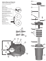
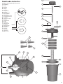
the filter connected to the outlet of a pump, water enters the unit through water inlet
(X). It is then forced to pass through the mechanical filtration stage, consisting of
foam filters that intercept and trap dirt and debris. Next, water reaches the biological
filtration* chamber where it comes into contact with beneficial bacteria. Finally, dirtfree water passes along the UV-C lamp unit (B), where it is exposed to UV rays that
inhibit algae growth. Water then returns to the pond through outlet (W).
*Pressure-Flo 1000/3000 UVC does not feature biological filtration.
BACKWASH-CLEANING SYSTEM
During operation, coarse debris is captured at the surface of the foam filters. As a
result, over time, the external surface of the foam filters will clog and hinder proper
filtration, because of reduced water flow. The limited water flow through the foam
filters reduces the effectiveness of both the biological and UV-C filtration. This
condition can easily be detected thanks to the cleaning indicator (U). Pressure-Flo
filters feature a unique Backwash-cleaning system that completely cleans the entire
surface of the mechanical foam filters. The complete cleaning operation can easily and
comfortably be done in a few minutes with no need to open the unit. Cleaning will
ensure that the filter will perform at optimal levels. Though the Backwash-Cleaning
System prolongs the time between maintenance sessions, thorough cleaning of the
unit is necessary periodically. See Cleaning and Maintenance of the Pressure-Flo Filter
for more details.
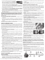
CLEANING INDICATOR
pressure. Never connect the filter to public water works.
• Orient the filter so that the water inlet (X), water outlet (W) and drain outlet (T)
point in the desired directions to avoid sharp bends in the hosing.
Hose connections
Pressure-Flo filter requires the connection of 3 hoses (not included): one for the inlet
of the unit (from the pond pump), one for the outlet which takes filtered water to the
pond, and one for discharging dirty water from the filter to a location outside the pond
during maintenance. When selecting and installing the hoses for your application,
maximize potential flow by choosing the largest diameter and shortest hosing possible
and avoiding kinks and sharp bends. Pressure-Flo Filters are equipped with 3 universal
click-fit couplings (H), which will make connecting and disconnecting the hosing
fast and easy. Connect flexible hoses to click-fit couplings and secure them with an
adequate hose clamp (not included).
IMPORTANT – Universal Click-Fit couplings (H) allow the connection of
different diameter flexible hosing, but it is important to cut off the unused
smaller diameter hose-tails to avoid flow restrictions.
When flexible hoses are securely connected to click-fit couplings, you can disconnect
hosing from the unit simply by pushing the click-fit coupling button and pulling. To
connect click-fit couplings to the unit, insert them onto the male connectors located on
the lid of the unit and ensure that the coupling button comes up fully.
Water Inlet (X): the Water Inlet is where pond water enters the Pressure-Flo filter.
Simply connect the outlet of a Laguna Max-Flo solids handling pump to the PressureFlo inlet (X) using non-kink hosing. The pump delivers dirty water from the pond to
the Pressure-Flo filter.
Water Outlet (W): the Water Outlet returns filtered water to the pond when the
filter is operating in filtering mode. Hosing attached to the water outlet (W) can be
placed directly in the pond or used to create a watercourse or waterfall. This outlet
is activated when the Mode Selector Switch (V) is pointing at the water outlet (W)
(Filtering Mode). The end of the outlet hosing should be placed as far away from the
pump inlet as possible to maximize water circulation in the pond.
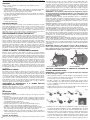
Drain Outlet (T): the Drain Outlet is where dirty water exits the filter when using the
Backwash-Cleaning System. Connect a hose to the Drain Outlet to allow dirty water
to drain out of the filter and into your garden (See Tip below). This outlet is activated
when the Mode Selector Switch (V) is pointing at the Drain Outlet (T) (Drain Mode).
IMPORTANT – During normal “Filtering Mode” operation, close the Drain
Outlet (T) using the Click-fit Sealing Cap (I).
Tip: dirty pond water is nutrient-rich and chlorine-free and is
particularly good for watering the garden.
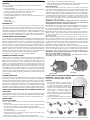
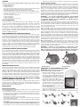
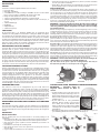
FILTERING MODE
DRAIN MODE
FILTER START-UP, OPERATION AND BACKWASH CLEANING
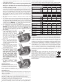
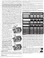
This unit features a cleaning indicator (U), which lets you know when the filter needs IMPORTANT! – Before the first and every
backwashing or cleaning. The height of the red cleaning indicator is approximately start-up after cleaning filter verify the
proportional to the filter clogging level. When the red indicator is low, the filter is following:
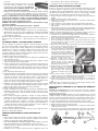
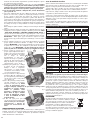
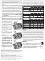
clean. When the red indicator is fully exposed, the filter needs cleaning. The cleaning • Before the first start-up, it is necessary to install
indicator may be affected by many variables, such as waterfall height and pump
the lid O-ring (P), which is supplied in a separate
P
performance. Its operating characteristics have been calibrated according to specific
poly bag. This O-ring must be correctly inserted
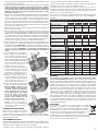
application conditions indicated in the chart (selecting the right Pressure-Flo and maxin its seat at the top of the filter canister (Fig. 1).
Flo pump for your Pond). Different application conditions may lead to different results. • This filter comes with the UVC lamp already
installed. Before connecting the filter to the
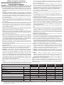
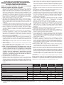
SELECTING THE RIGHT PRESSURE-FLO AND MAX-FLO PUMP FOR
power supply, it is necessary to perform the
YOUR POND
Filter Wet Test. Refer to the section “Changing
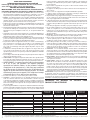
Using the “filter specification” table, select the correct Laguna Max-Flo pump/Pressure-Flo
the UV-C Lamp and Cleaning the Quartz Sleeve”
Fig. 1
filter combination according to your pond size and conditions. Due to the high number
for detailed instructions.
of variables, the following recommendations are offered as general guidance only.
• The Biological Media must be placed in the Filter
Case as indicated in the picture (except Pressure-Flo 1000/3000 UV-C)(Fig. 2).
INSTALLATION
Location of the filter
3
Choose a suitable location for your Pressure-Flo filter, keeping in mind the following
recommendations:
• Place the Pressure-Flo Filter on a firm and level base, where it is safe from flooding
and has enough ventilation. Protect the appliance from direct sunlight.
• Place either above ground or buried with the lid clamp (O) at least 5 cm/2 inches
above ground level.
• To avoid overheating, do not cover the filter.
• Place the filter at least 1 meter/3.2 feet from the pond edge and make sure it
cannot fall into the water in any way.
• Make sure you have full access to the lid of the unit for maintenance.
• Do not operate the filter with a water pressure greater than 0,4 bar or 5.8 PSI of
Fig. 2
• Ensure that the lid (G) is securely closed with the lid clamp (O) and the lid O-ring