1
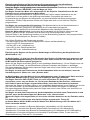
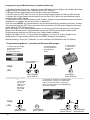
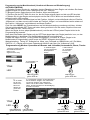
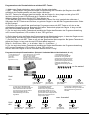
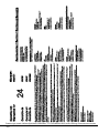
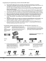
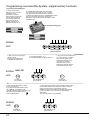
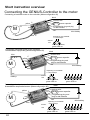
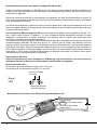
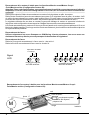
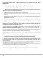
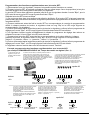
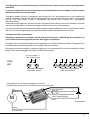
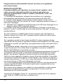
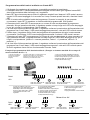
Connecting a conventional motor for the functions forward / motor stop / brake / reverse (motor
mode #3)
In this mode, only half the indicated permanent current drain is available. In addition, only
batteries of max. 9.6V may be connected in this mode!
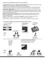
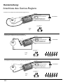
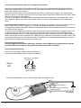
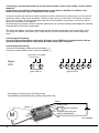
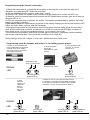
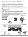
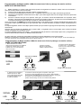
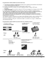
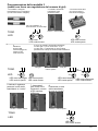
Connect or solder the outer blue motor connector A of the controller to the motor input (-). Connect the
yellow (the other outer) motor connector C directly to the input (+) of the motor. The central connector
isn't in use. In case your motor turns the wrong way round, swap the connectors on the motor. Never
swap the connectors on the battery!
On switching the controller ON the controller determines the connector settings and adapts the software
automatically to this motor configuration.
The motor and battery connector cables should all be the same length and never longer than 12cm.
The longer the cables, the heavier your model will be, and the more interference will be radioed by
them.
Connecting to the battery:
Use only high-quality batteries offered by Graupner Ltd or GM-Racing. Using batteries with an
increased internal resistance may lead to the destruction of the controller!
Connecting to the battery:
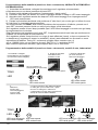
Connect the red battery cable to the drive battery (+).
Connect the black battery cable to the drive battery (-).
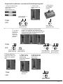
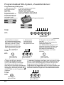
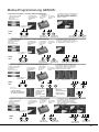
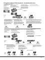
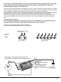
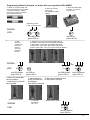
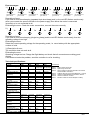
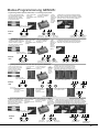
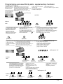
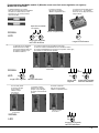
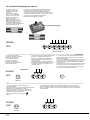
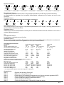
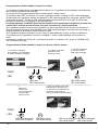
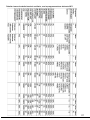
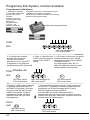
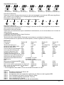
depending on the MODE
1-4 short beeps
Signal
LED
red gn
rot
...
...
red gn
rot
red gn
rot
red LED flashes,
green LED on
red gn
rot
red gn
rot
red gn
rot
red gn
rot
red gn
rot
red LED flashes 6x,
green LED on
Connecting a brushed motor for the functions
forward/Motor stop/brake/reverse (Motorconfiguration #3)
black
-
+
M
-
8
red
B
A
Programming plug and
plug for hall sensors
red
blue
A
-
power capacitor
C
+
+
receiver wire
yellow C
drive battery