1
INSTALLATION
English
General
6. Place the unit in the desired location. Two people are
required for this step.
Hatco macho Nacho Chip Warmers are shipped with most
components installed and ready for operation. The following
installation instructions must be performed before plugging in
and operating the cabinet.
®
• Locate the unit in an area where the ambient air
temperature is constant and a minimum of 70° F (21° C).
avoid areas that may be subject to active air movements
or currents (i.e., near exhaust fans/hoods and air
conditioning ducts).
WARNING
• make sure the unit is at the proper counter height in an
area convenient for use.
ELECTRIC ShOCK hAzARD: Unit is not weatherproof.
Locate unit indoors where the ambient air temperature is
a minimum of 70°F (21°C).
• make sure the countertop is level and strong enough to
support the weight of the unit and food product.
FIRE hAzARD: Locate unit a minimum of 1″ (25 mm) from
combustible walls and materials. If safe distances are not
maintained, discoloration or combustion could occur.
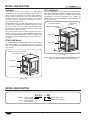
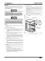
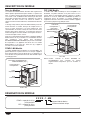
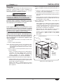
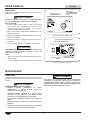
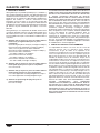
Decal (3)
Chip
Deflector
CAUTION
Locate unit at the proper counter height in an area that is
convenient for use. The location should be level to prevent
the unit or its contents from falling accidentally and strong
enough to support the weight of the unit and contents.
Transport unit in upright position only. Before moving or
tipping unit, secure all glass surfaces, doors, pan rails,
and/or skirts with tape. Failure to do so may result in
damage.
Chip
Deflector
Flange
1. Remove the unit from the carton. Two people are required
for this step.
Pin
2. Remove the information packet.
Floor Panels
w/ Holes
NOTE: To prevent delay in obtaining warranty coverage,
complete online warranty registration. See the
ImPORTaNT OWNER INFORmaTION section for
details.
3. Remove tape and protective packaging from all surfaces of
the unit, shelves, and any accessories.
assembling a FDWD-1-mN model
• Legs — The cabinets are shipped with four rubber feet
attached to the bottom of the unit. For cabinets with the
accessory 4″ (102 mm) adjustable legs, see the
OPTIONS aND aCCESSORIES section for installation
instructions.
4. Install the chip deflector behind the upper door.
• FDWD-1-mN models—Two holes on the chip deflector
flange slide over two pins at the bottom of the upper door
frame.
• FST-1-mN models—The chip deflector flange slides
behind the flange at the bottom of the upper door frame.
5. Install the decals on the three side panels above the glass
side panels.
a. Clean the side panels with a non-oily cleaner, such as
rubbing alcohol.
b. When the side panels have dried, remove the protective
backing from the decal and apply it to the panel.
c. Remove any air pockets or bubbles behind the decal by
rubbing gently with a soft cloth, working from the center
of the decal towards the outer edges.
Form No. mNm-0613
7