1
ENGLISH
ESPAÑOL
320 S - 326 S
320 S
320 S
INSTALLATION
Refer to the general installation instructions on pgs. 12,14,16. In addition
follow the following instructions:
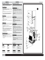
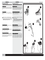
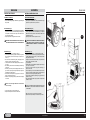
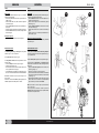
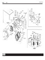
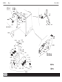
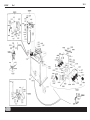
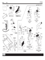
» Install the air cylinder behind the column using the two M8 bolts
supplied (fig. 31a);
» Connect the rubber hose to the cylinder connector and tighten the
connector band (fig. 31b).
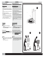
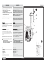
» Connect the gauge holder to the column with the two M6 bolts supplied (fig. 32);
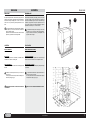
» Connect the air line hose to the connector on the filter unit (see fig. 33).
» Connect the small air hose to the quick connector, inserting it into the
relevant hole (fig. 34).
INSTALACION
Haga referencia a las modalidades generales de instalación de pág. 8-910. Además, siga las siguientes instruc-ciones:
» Instale la bombona del aire detrás de la columna aplicando los dos
tornillos de equipo de M8 (fig. 31a).
» Introduzca el tubo de goma en la unión de la bombona y apriete la
abrazadera. (fig. 31b).
» Conecte el soporte del manómetro a la columna con los dos tornillos de equipo de M6 (fig. 32).)
» Conecte el tubo del aire de línea con la unión de la unidad filtro (vea
fig. 33).
» Conecte el tubo del aire a la conexión rápida introduciéndolo en el
orificio apropiado (fig. 34).
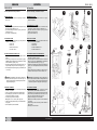
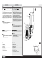
Mounting the safety belts.
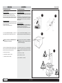
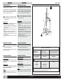
If there is a safety belt provided, install it as shown in figure 35.
Montaje de los cinturones de seguri-dad:
Si la máquina está dotada de los cinturones de seguridad, hay que instalarlos
según indica la fig. 35.
INSTRUCTIONS FOR USE
INSTRUCCIONES PARA EL USO
For bead-breaking, demounting and mounting tires, see the general
instructions on pgs. 11 and 12 of this manual.
Para las operaciones de Destalo-na-miento, Desmontaje y Montaje del
neu-má-tico haga referencia a las instruc-ciones generales de la pág. 11
y 12 del presente manual.
31a
31b
32
33
34
For the pedal controls refer to the key on pg. 26.
Para los mandos de pedal, haga referencia a la explicación de pág. 27.
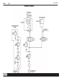
For seating beads and inflation, after mounting the wheel on the rim
proceed as follows:
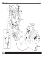
» If there is a safety belt, fit it as shown in fig. 30a on pg. 26.
» Attach the air hose to the tire valve;
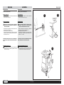
» Raise the tire with both hands to allow the air (which comes out of the
tracks) to get between rim and tire (fig. 36);
» Press the inflation pedal (I) completely down to obtain the air output fro
the tracks. At the same time release the tire to allow the bead to set.
N.B.: Whenever the bead does not seat in, repeat all the stages in the
above sequence.
When the tire is seated, continue inflation by pressing the pedal in the
intermediate position until the desired pressure is reached.
Para las operaciones de talo-na-miento y de hinchamiento, después
de haber montado el neumático sobre la llanta, continúe siguiendo estas
indica-ciones:
» Aplique los cinturones de seguridad, si están en dotación, como
muestra la fig. (30a pág. 26).
» Introduzca el tubo del aire en la válvula del neumático;
» Levante el neumático hacia arriba con ambas manos, consentiendo al
aire (que sale por los orificios de los recorridos) de entrar entre llanta
y neumático (fig. 36);
» Apriete el pedal de hinchamiento (I) hasta el tope del recorrido, para
obtener la salida del aire de los recorridos y contemporáneamente
relaje el neumático para consentir su talo-namiento.
35
36
NOTA: Si el neumático ne se intalona, repita las operaciones descritas
arriba con más cuidado.
Cuando haya talonado el neumático, continúe la operación de
hinchamiento apretando el pedal apropiado (I) en la posición intermedia,
hasta el alcance de la presión deseada.
COD. 103932 Rev.0
14