1
English
Water connections
Automatic water valves
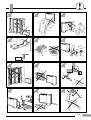
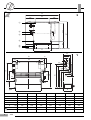
(See fig.24-25-26)
The fan coils can be equipped with valves, both in 2-pipe or 4-pipe
versions.
We recommend using the valves in order to prevent condensate formation on the unit when the fan is not working and room
humidity is very high.
The valve heads are thermal type with 230V power supply, average
consumption 5 VA, maximum operating pressure
1600 kPa.
opening time depends on the
temperature and is from 120 to 240 seconds.
The tightness of the connections is ensured by a rubber sealing (ORING) inserted in the connection (tightening torque 30 Nm).
If valves are installed by the installer (accessories), do not forget to
use the
(O-RING) sealing ring supplied.
The accessory motorized valve can also be supplied with a shut-off
valve and holder for water flow control and for unit disconnection
from the system.
The motorized valves can be 3-way with bypass or 2-way.
Make sure that all unit pipe connections are aligned and well
supported, to prevent abnormal strains on the unit.
Check for leaks after the system has been filled with water.
Remember to mount the auxiliary drain pan under the valve group
inserting the drain pipe into the proper hole.
The manufacturer cannot guarantee seal quality and tightness of
the valve group provided by the installer (which is therefore not
factory tested). The manufacturer thus declines all responsibility for
possible malfunction of said items and for damage resulting from
leaks in said items.
Electrical connections
IMPORTANT:
• Make earth connection prior to any other electrical
connections.
• Disconnect the power supply to all circuits prior to handling
any electrical components.
to the EN 60335-2-40 standard.
• For the unit power supply, it is recommended to use cables
with a minimum size of 3G1.5 mm2.
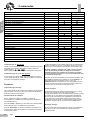
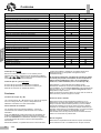
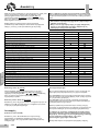
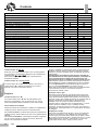
• For units equipped with electric heater, refer to table III
(Technical data of electric heater) for sizing power supply
cables.
• Make sure that connection to the mains supply of the electric
heater is made through a switch with contact gap of 3 mm.
• After making all electrical connections do not forget to close
the control box panel using the special protective cover and
to fix it by means of the screw/s previously removed.
• Remove the control box panel casing by means of the fixing
screw/s.
• Before proceeding with the unit connection to the mains supply
locate live L and neutral N, then make connections as shown in
the wiring diagram.
• According to the installation instructions, the disconnecting
switches from the mains power supply should have a contact gap
(4 mm) such that total disconnection can be ensured under the
conditions provided for by overvoltage class III.
• All fan coil connecting cables as well as accessory wires
must be of the H05 VV-F, type with PVC insulation according
Control box panel
The control box panel is always positioned opposite the water
connections.
• Two different control box panels are available: one for a unit
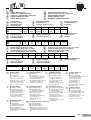
without electric heater (See fig.27), and one for a unit with electric
heater (See fig.28). Each control box panel is equipped with
terminal blocks for electrical connections (see wiring diagrams).
Connect the cables to the terminal blocks and secure the cables
using the special cables holders.
• If the unit is fitted with an electric heater, this must have a
separate power supply.
Connect the power supply mains L and N (neutral) to terminal 7
according to the suitable polarity. Connect the ground wire to the
machine structure (screw under the control box panel). All units are
equipped with a fuse that protects the machine/controls. If this fuse
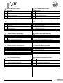
needs to be replaced, refer to table II (POWER SUPPLY FUSE).
Controls
Upon request, the 42N series fan coil can be equipped with one of
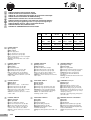
three types of controls: one electromechanical (U) (See fig.29) and
two electronic versions, regulated by a microprocessor (A and B)
(See fig.30-31).
All three controls can be mounted either on the fan coil or on the
wall.
All controls must be opened and installed only by qualified
personnel as they contain electrical and electronic components,
connected to 230V power supply.
WARNING:
• Disconnect the power supply before opening the control cover.
Each control regulates a single fan coil (alternatively with a relay
board it is possible to regulate several units with a single control
see accessories).
• All inputs (external contact, seasonal changeover etc.) must
be electrically insulated consistent with 230V requirements.
42N
19