1
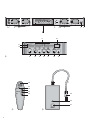
24 FULL-Taste; solange die Taste gedrückt ist, werden alle Lampen auf ihre volle Leistung geschaltet
●
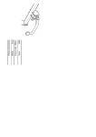
1.3 Infrarot-Empfänger (Abb. 3)
25 RJ45-Stecker zum Anschluss des IR-Empfängers an die Buchse REMOTE CONTROL (6) am
Dimmer; beim Herausziehen des Steckers die
Entriegelung am Stecker drücken
26 Kontroll-LED; leuchtet, wenn der IR-Empfänger an
den eingeschalteten Dimmer angeschlossen wird
●
●
27 Fenster für den IR-Sensor; hierauf die Fernbedienung richten
2
Soll das Gerät endgültig aus dem
Betrieb genommen werden, übergeben
Sie es zur umweltgerechten Entsorgung
einem örtlichen Recyclingbetrieb.
Hinweise für den sicheren Gebrauch
Dieses Gerät entspricht allen erforderlichen Richtlinien der EU und ist deshalb mit
gekennzeichnet.
WARNUNG Das Gerät wird mit lebensgefährlicher Netzspannung (230 V~) versorgt. Nehmen Sie deshalb niemals
selbst Eingriffe am Gerät vor, die
nicht in dieser Anleitung beschrieben
sind. Durch unsachgemäßes Vorgehen besteht die Gefahr eines elektrischen Schlages.
Beachten Sie auch unbedingt die folgenden Punkte:
●
Verwenden Sie das Gerät nur im Innenbereich
und schützen Sie es vor Tropf- und Spritzwasser,
hoher Luftfeuchtigkeit und Hitze (zulässiger Einsatztemperaturbereich 0 – 40 °C).
●
Stellen Sie keine mit Flüssigkeit gefüllten Gefäße,
z. B. Trinkgläser, auf das Gerät.
●
Nehmen Sie das Gerät nicht in Betrieb oder
trennen Sie es sofort von der Netzspannung,
1. wenn sichtbare Schäden am Gerät oder an der
Netzanschlussleitung vorhanden sind,
2. wenn nach einem Sturz oder Ähnlichem der
Verdacht auf einen Defekt besteht,
1.3 Infrared receiver (fig. 3)
3
Einsatzmöglichkeiten
Der DPB-40DMX ist ein 4-Kanal-Dimmer zur effektvollen Lichtgestaltung z. B. auf der Bühne oder in
der Diskothek. Er kann über ein DMX-Steuergerät
gesteuert werden. Dabei kann die DMX-Adresse für
jeden Kanal individuell gewählt werden. Alternativ ist
ein eigenständiger Betrieb möglich, mit der Option,
weitere Dimmer zu steuern. Im eigenständigen
Betrieb stehen mehrere Betriebsarten mit wählbaren Lauflichtprogrammen und mit Musiksteueroption
über das eingebaute Mikrofon zur Auswahl.
Generell ist ein Betrieb als Schalter oder als Dimmer mit einstellbarer Leistungsbegrenzung und einstellbarem Mindestwert (z. B. zur Vorheizung der
Lampen) möglich.
Über die mitgelieferte Infrarot-Fernbedienung
kann der Dimmer auch z. B. von der Bühne aus einfach bedient werden. Durch seine Bauform und das
mitgelieferte Montagematerial zur Befestigung der
Scheinwerfer lässt er sich zudem auf einem Stativ
als Traverse einsetzen.
●
No guarantee claims for the unit and no liability for
any resulting personal damage or material
damage will be accepted if the unit is used for
other purposes than originally intended, if it is not
correctly installed, operated, or not repaired in an
expert way.
If the unit is to be put out of operation
definitively, take it to a local recycling
plant for a disposal which is not harmful
to the environment.
Safety Notes
This unit corresponds to all required directives of the
EU and is therefore marked with
.
WARNING
The unit is supplied with hazardous
mains voltage (230 V~). Never make
any modifications on the unit not
described in this instruction manual.
Inexpert handling may cause an electric shock hazard.
It is essential to observe the following items:
● The unit is suitable for indoor use only. Protect it
against dripping water and splash water, high air
humidity, and heat (admissible ambient temperature range 0 – 40 °C).
● Do not place any vessels filled with liquid, e. g.
drinking glasses, on the unit.
● Do not set the unit into operation, or immediately
disconnect the mains plug from the mains socket if
1. there is visible damage to the unit or to the
mains cable,
2. a defect might have occurred after a drop or
similar accident,
3. malfunctions occur.
The unit must in any case be repaired by skilled
personnel.
● Never pull a mains cable to disconnect the mains
plug from the mains socket, always seize the plug.
● For cleaning only use a dry, soft cloth, by no
means water or chemicals.
4
Montage
Das Gerät muss fachgerecht und sicher montiert
werden. Das Gehäuse besitzt auf der Ober- und
Unterseite zur Befestigung ein Profil, in das der Kopf
einer M10-Schraube passt. Darüber lässt sich zum
einen der Dimmer befestigen, zum anderen können,
über die mitgelieferten Schrauben, die Lampen (z. B.
PAR-64... oder PAR-56... von „img Stage-Line“) am
Dimmer befestigt werden.
Den Dimmer mithilfe des beiliegenden TV-Zapfens auf einem geeigneten Stativ (z. B. PAST400/SW mit Reduzieradapter PAST-20/SW von
„img Stage Line“) befestigen:
D
A
CH
1) Das Seitenteil (8) abschrauben.
2) Die Köpfe der Lampenbefestigungsschrauben
und der Schraube des TV-Zapfens in der richtigen
Reihenfolge in die untere Nut schieben. Bei
Bedarf auch Schrauben zur Lampenbefestigung
in die obere Nut einschieben.
3) Das Seitenteil wieder aufsetzen und festschrauben.
25 RJ45 plug for connection of the IR receiver to the
jack REMOTE CONTROL (6) at the dimmer;
when removing the plug, press the unlocking
device at the plug
26 Indicating LED; lights up when the IR receiver is
connected to the dimmer switched on
27 Window for the IR sensor; direct the remote control to this window
2
3. wenn Funktionsstörungen auftreten.
Lassen Sie das Gerät in einer Fachwerkstatt reparieren.
Ziehen Sie einen Netzstecker nie an der Zuleitung
aus der Steckdose. Fassen Sie immer am Stecker
an.
Verwenden Sie für die Reinigung nur ein trockenes, weiches Tuch, niemals Wasser oder Chemikalien.
Wird das Gerät zweckentfremdet, falsch installiert, nicht richtig bedient oder nicht fachgerecht
repariert, kann keine Haftung für daraus resultierende Sach- oder Personenschäden und keine
Garantie für das Gerät übernommen werden.
3
Applications
The DPB-40DMX is a 4-channel dimmer for effective illumination e. g. on stage or in the discothèque.
It can be controlled via a DMX control unit. The DMX
address can individually be selected for each channel. Alternatively, an independent operation is possible, with the option to control further dimmers.
During independent operation, several operating
modes with selectable light sequencing programmes and with the option of music control via the
integrated microphone can be selected.
Generally, the operation as a switch or dimmer
with adjustable power limitation and adjustable minimum value (e. g. for preheating of the lamps) is possible.
Via the supplied infrared remote control the dimmer can also easily be operated e. g. from the stage.
Due to its design and the supplied mounting material
for fixing the lamps it can in addition be used on a
stand as a cross arm.
4
Mounting
4) Den TV-Zapfen am Dimmer mittig ausrichten und
festziehen.
5) Den Dimmer mit dem TV-Zapfen auf das Stativ
aufsetzen und fixieren.
6) Die Lampen an den Schrauben befestigen und so
ausrichten, dass eine Balance zwischen der linken
und rechten Seite besteht und das Stativ einen
sicheren Stand hat. Gegebenenfalls die Position
der Lampen oder des TV-Zapfens korrigieren.
Unbedingt darauf achten, dass die Tragfähigkeit
von max. 4 kg pro Lampenbefestigungsschraube
und die max. verteilte Tragfähigkeit von 16 kg
(durch das Gesamtgewicht der Lampen) nicht
überschritten wird!
7) Die Lampen zusätzlich mit Sicherungsseilen so
am Dimmer befestigen, dass sie bei unbeabsichtigtem Lösen der Schraubbefestigung nicht mehr
als 20 cm fallen können.
Alternativ zur Stativmontage kann der Dimmer auch
mit zwei ausreichend belastbaren Lampenbefesti-
(e. g. PAR-64... or PAR-56... from “img Stage Line”)
can be fixed to the dimmer via the supplied screws.
Fix the dimmer by means of the supplied TV spigot on a suitable stand (e. g. PAST-400/SW with
reducing adapter PAST-20/SW from “img Stage
Line”).
1) Screw off the side part (8).
2) Insert the heads of the lamp fixing screws and of
the TV spigot screw into the lower groove in the
correct order. If required, also insert the lamp
fixing screws into the upper groove.
3) Reposition the side part and tighten the screws.
4) Align the TV spigot centrally at the dimmer and fix
it.
5) Place the dimmer with the TV spigot on the stand
and fix it.
6) Fix the lamps at the screws and align them so
that there is a balance between the left side and
the right side and that the stability of the stand is
ensured. If required, readjust the position of the
lamps or TV spigot. Pay in any case attention that
the maximum load capacity of 4 kg for each lamp
fixing screw and the maximum distributed load
capacity of 16 kg (by the total load of the lamps)
will not be exceeded!
7) Additionally fix the lamps with safety ropes to the
dimmer so that the maximum falling distance of
the lamps is 20 cm in case the screw fixing
should getting loose unintentionally.
Alternatively to the stand mounting, the dimmer can
also be suspended from a cross arm with two lamp
fixing hooks with M10 screws capable of carrying a
sufficient load. Instead of the TV spigot screw at the
lower side of the housing, the screws of the fixing
hooks are inserted into the upper groove of the dimmer housing and screwed with the hooks. The
lamps are fixed as described before.
GB
The unit must safely be mounted in an expert way.
For fixing, the housing is equipped on the upper and
lower sides with a profile into which the head of an
M10 screw fits. On the one hand, the dimmer can be
fixed via this profile, on the other hand the lamps
5