1
Menu
06
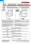
MANUALE USO E MANUTENZIONE
USE AND MAINTENANCE MANUAL
AVVOLGITUBO AUTOMATICI
AUTOMATIC HOSE REELS
A
DIMENSIONI - DIMENSIONS
Installazione con giunto
girevole eccentrico.
Installation with eccentric
swivel joint
Installazione con giunto
girevole centrato.
Installation with centered
swivel joint
CARATTERISTICHE - CHARACTERISTICS
Gli avvolgitubo modello BG sono costruiti in lamiera d'acciaio stampata e verniciata a polveri epossidiche.
Gli avvolgitubo modello BGX sono invece in acciaio inox AISI
304. Non sono adatti per distribuire fluido per processo alimentare
ma solamente per soluzioni varie di lavaggio. Inoltre non devono
essere posizionati in zone che possono venire a contatto con
prodotti alimentari.
Gli apparecchi riavvolgono automaticamente il tubo mediante una
molla in acciaio di alta qualità incorporata nel tamburo e permettono di arrestarlo alla lunghezza voluta tramite un dispositivo automatico.
Questi avvolgitubo devono essere utilizzati esclusivamente
per la distribuzione di fluidi alle pressioni e temperature indicate nelle tabelle. Si declina ogni responsabilità per anomalie o
pericolosità che derivano dal montaggio di tubi con caratteristiche ed impieghi diversi da quelli descritti.
DICHIARAZIONE DI CONFORMITA'
Si dichiara che gli avvolgitubo BG e BGX sono conformi alla
direttiva macchine 98/37 CE e successivi aggiornamenti.
Inoltre sono state applicate le seguenti norme armonizzate:
- EN 292/1, EN 292/2: "Sicurezza del macchinario: Principi
Fondamentali di Progettazione".
- EN 294: "Sicurezza del macchinario: Distanze di sicurezza
per impedire il raggiungimento di zone pericolose con gli
arti superiori".
Busca, 06.02.2007
TORINO RENATO
COSTRUZIONI MECCANICHE
BG - BGX
Installazione a parete, soffitto o a pavimento. Wall, ceiling or floor installation
The hose reels models BG are made of moulded steel and painted
with electrostatic powder system.
The hose reels models BGX are made of stainless steel AISI 304.
They are not suitable for distribution of fluid for food process but
only for different kinds of washing. These hose reels have not to
be placed in areas where they might be in contact with food
products.
The hose rolling is done automatically by a spring made of high
quality iron, incorporated in the drum.
The stop can be done at any desired length, through an automatic
locking device.
These hose reels have to be used only for distributing fluids,
at the pressures and temperatures indicated on the schedule.
We decline any responsibility for anomalies or dangers which could
arise by the assembly of hoses with characteristics and uses
different from the ones described herein.
DECLARATION OF CE CONFORMITY
We hereby declare that the hose reels BG and BGX are
manufactured in conformity to the 98/37 EC directive and
following modifications.
Besides, the following harmonized rules have been applied:
- EN 292/1, EN 292/2: "Safety of the machine: General design
methods".
- EN 294: "Safety of the machine: Safety distances to prevent
danger zones being reached by the upper limbs".
Torino Renato
General Manager
S. Chiaffredo - Strada Antica di Cuneo, 43 - 12022 BUSCA (CUNEO) ITALY
Tel. (+39+171) 93.71.52 - Fax (+39+171) 93.73.02
CARATTERISTICHE TECNICHE - TECHNICAL CHARACTERISTICS
FLUIDO
FLUID
PRESSIONE MAX.
MAX. PRESSURE
CODICE
CODE
* ENTRATA Gas
INLET Bsp
TUBO DIAM.
HOSE DIAM.
LUNGH.TUBO
HOSE LENGTH
ACQUA / WATER
80° C Max.
10 Bar / 140 PSI
Tubo antimacchia
Stainproof hose
BGX101325K
BGX101330K
BGX101625K
BGX101920K
BGX102515K
1/2" F
1/2" F
1/2" F
3/4" F
1" F
13 x 21
13 x 21
16 x 24
19 x 27
25 x 34
25 m / 80 ft
30 m / 100 ft
25 m / 80 ft
20 m / 65 ft
15 m / 50 ft
18 Bar / 250 PSI
Tubo in gomma
Rubber hose
BG181325
BG181330
BG181625
BG181920
BG182515
1/2" F
1/2" F
1/2" F
3/4" F
1" F
13 x 20
13 x 20
16 x 23
19 x 27
25 x 34
25 m / 80 ft
30 m / 100 ft
25 m / 80 ft
20 m / 65 ft
15 m / 50 ft
60 Bar / 850 PSI
BG601225
BG601230
BG605825
BG603420
BG600115
1/2" F
1/2" F
1/2" F
3/4" F
1" F
1/2"
1/2"
5/8"
3/4"
1"
25 m / 80 ft
30 m / 100 ft
25 m / 80 ft
20 m / 65 ft
15 m / 50 ft
400 Bar / 5600 PSI
BG4G3825
BG4G3830
3/8" F
3/8" F
3/8"
3/8"
25 m / 80 ft
30 m / 100 ft
400 Bar / 5600 PSI
Tubo antimacchia
Stainproof hose
BG4H3825
BGX4H3825
BG4H3830
BGX4H3830
3/8"
3/8"
3/8"
3/8"
F
F
F
F
3/8"
3/8"
3/8"
3/8"
blue
blue
blue
blue
25 m / 80 ft
25 m / 80 ft
30 m / 100 ft
30 m / 100 ft
BG3H1225
BGX3H1225
BG3H1230
BGX3H1230
1/2"
1/2"
1/2"
1/2"
F
F
F
F
1/2"
1/2"
1/2"
1/2"
blue
blue
blue
blue
25 m / 80 ft
25 m / 80 ft
30 m / 100 ft
30 m / 100 ft
Avvolgitubo senza tubo
Hose reels without hose
FLUIDO
FLUID
PRESSIONE MAX.
MAX. PRESSURE
CODICE
CODE
ENTRATA Gas
INLET Bsp
CAPACITA' MAX.
MAX. CAPACITY
18 Bar / 250 PSI
BG181230ST
1/2" M
30 m / 100 ft
ARIA / AIR
ACQUA / WATER
40°C Max.
ARIA / AIR
OLIO / OIL
ACQUA / WATER
150°C Max.
GRASSO / GREASE
60 Bar / 850 PSI
BG600125ST
BGX600125ST
1" M
(1") 15 m / 50 ft
(3/4") 20 m / 65 ft
(5/8") 25 m / 80 ft
400 Bar / 5600 PSI
BG4H1230ST
BGX4H1230ST
1/2" M
30 m / 100 ft
400 Bar / 5600 PSI
BG4G3830ST
3/8" F
80 ft / 25 m
OLIO / OIL
ACQUA / WATER
40°C Max.
GRASSO / GREASE
Avvolgitubo completi di tubo
Hose reels with hose
ACQUA / WATER
150°C
300 Bar / 4200 PSI
Tubo antimacchia
Stainproof hose
* Raccordo del tubo di collegamento / Fitting of the connection hose
-
INSTALLAZIONE
ATTENZIONE! L'INSTALLAZIONE DELL'AVVOLGITUBO ED
IL COLLEGAMENTO ALLA RETE E' CONSENTITO SOLTANTO A PERSONALE TECNICO SPECIALIZZATO.
IMPORTANTE: L'avvolgitubo deve essere collocato a parete
o a soffitto ad un'altezza minima dal pavimento di 2,50 m per
evitare incidenti durante le operazioni di lavoro.E' possibile il
montaggio a pavimento o come accessorio su altre macchine soltanto se viene applicata una protezione di tipo fisso.
Montare l'avvolgitubo su una superficie rigida e consistente
impiegando 4 tasselli diametro 10 mm.
Scegliere, tra le tre alternative proposte, la posizione più idonea per l'uscita del tubo (vedi figura A).
Per spostare Il braccio guidatubo nella posizione desiderata
rimuovere il coperchio in plastica in modo da accedere alle viti
di serraggio (vedi figura B).
Collegare sempre l'avvolgitubo alla rete di alimentazione mediante un tubo flessibile con lunghezza 700 mm.
Sulla rete applicare un rubinetto a sfera in modo da facilitare le
operazioni di manutenzione e da utilizzare come valvola di emergenza per situazioni pericolose.
ATTENZIONE! La ditta costruttrice declina ogni responsabilità per danni a persone o cose causate da un montaggio
non corretto dell'avvolgitubo.
B
-
INSTALLATION
WARNING: THE INSTALLATION OF THE HOSE REEL AND
THE CONNECTION TO THE PIPING NETWORK ARE
ALLOWED TO QUALIFIED PERSONNEL ONLY.
IMPORTANT: The hose reel has to be wall or ceiling
mounted at a minimum height from the floor of 2.50 m in
order to prevent accidents during work operations.It is
possible to mount it on the floor or on other machines as
an accessory only when complete with a fixed support.
Mount the hose reel on stiff and consistent surface, using 4
dowels of 10 mm diameter.
Choose the most suitable position for the hose outlet among
the three alternatives suggested (see ill. A).
To move the hose-guide-arm in the desired position, remove
the plastic cover in order to reach the fastening screws. (see
ill. B).
Always connect the hose reel to the piping network by the
700 mm flexible hose.
Put a ball-tap on the piping network of the hose reel in order
to make the maintenance operations easier. The said ball-tap
can be used as a safety valve for dangerous situations.
WARNING! The manufacturer declines any responsibility
for injuries to people or damages to things caused by a
wrong assembly of the hose reel.
1
2
MONTAGGIO DEL TUBO (Modelli senza tubo)
1)
2)
3)
4)
5)
ATTENZIONE! NON INSERIRE LE MANI ALL'INTERNO
DELL'AVVOLGITUBO QUANDO SI FA RUOTARE IL TAMBURO!
Montare l'avvolgitubo sulla superficie e nella posizione stabilita.
Inserire il tubo attraverso i rullini di guida, collegarlo al raccordo
del giunto girevole e stringere con la chiave adatta.
Ruotare il tamburo manualmente in modo da avvolgere tutto il
tubo.
Afferrare l'estremità del tubo e far ruotare di alcuni giri il tamburo
nel senso opposto in modo da precaricare la molla.
Inserire nuovamente l'estremità del tubo attraverso i rullini di guida e montare il tampone di arresto alla distanza desiderata.
Srotolare e arrotolare interamente il tubo per verificare il corretto
funzionamento.
Per i modelli forniti con il tubo seguire le istruzioni descritte a partire dal punto 3.
1)
2)
3)
4)
5)
3
HOSE ASSEMBLY (Models without hose)
WARNING! DO NOT PUT YOUR HANDS INSIDE THE
HOSE REEL WHEN YOU ROTATE THE DRUM!
Mount the hose reel on the required surface and position.
Put the hose between the guide rollers, connect it to the
fitting of the swivel joint and tighten it by the suitable wrench.
Rotate manually the drum in order to rewind completely
the hose.
Hold the hose-end and rotate the drum for some turns in
the opposite direction to pre-load the spring.
Insert again the hose-end between the guide rollers and
put the hose rubber stopper at the desired length.
Unwind and rewind the hose completely to check the proper
operation of the hose reel.
For the models with hose follow the
instructions starting from point 3.
USO
Per avere la massima efficenza durante le operazioni di
lavoro si consiglia di svolgere il tubo soltanto per la lunghezza necessaria.
Il tubo puo essere bloccato nella posizione voluta ad ogni
giro del tamburo.
Per riavvolgere il tubo esercitare una lieve trazione su di esso.
E' importante sempre trattenere il tubo durante il
riavvolgimento per impedire danni all'apparecchio, a
persone o cose circostanti.
USE
To get the maximum efficiency during work operations, we
suggest that you unroll the hose for the required length only.
The hose can be stopped at the desired length at every turn
of the drum.
To rewind the hose, put a light traction on it.
Always hold the hose when you rewind it in order to avoid
damages to the machine, injuries to people or to
surrounding things.
MANUTENZIONE
IMPORTANTE! Qualsiasi operazione di manutenzione
deve essere eseguita da personale opportunamente addestrato.
- Verificare regolarmente che:
1. L'avvolgitubo installato funzioni correttamente.
2. Non vi siano perdite di fluido dai raccordi del tubo e dal
giunto girevole.
3. Il tubo flessibile sia in buone condizioni.
- Per qualsiasi anomalia e prima di procedere ad eventuali
sostituzioni di pezzi si consiglia di interpellare la casa
costruttrice.
MAINTENANCE
IMPORTANT!: Any maintenance operation shall be
carried out by a suitably trained staff.
- Check periodically:
1. The correct operation of the hose reel.
2. That there are no fluid losses from the couplers and the
swivel joint.
3. The good condition of the flexible hose.
- We advise you to contact the manufacturer for any possible
anomaly and before replacing any part.
RIPARAZIONE
IMPORTANTE! Qualsiasi operazione di riparazione deve
essere eseguita da personale opportunamente addestrato seguendo le indicazioni date dal costruttore.
REPAIRS
IMPORTANT: Any maintenance operation shall be carried
out by a suitably trained staff following carefully the
information given in this manual.
- ATTENZIONE! Prima di eseguire qualsiasi intervento
sull'avvolgitubo é opportuno:
1. Chiudere l'alimentazione del fluido.
2. Togliere il tampone di arresto in gomma e rilasciare il
tubo lentamente in modo da scaricare completamente la
molla.
- WARNING! Before starting any operation in the reel:
1. Turn off the supply of fluid.
2. Remove the hose rubber stopper and release the hose
slowly untill the spring is completely unloaded.
- Verificare e sostituire periodicamente:
1. La guarnizione di tenuta all'interno del giunto girevole.
2. Il tubo flessibile.
- Qualsiasi sostituzione di pezzi costituenti l'avvolgitubo deve
essere fatta utilizzando ricambi originali.
- Le istruzioni relative alla sostituzione della molla, giunto
girevole e guarnizioni sono allegate ai pezzi di ricambio.
- Check and replace periodically:
1.The seal inside the swivel joint.
2.The flexible hose.
- Any replacement of hose reels parts has to be done using
original spare parts.
- Instructions for the replacement of the spring, the swivel
joint, and the seals come with each spare part.
SOSTITUZIONE DEL TUBO
1)
2)
3)
4)
5)
6)
7)
8)
9)
NON INSERIRE LE MANI ALL'INTERNO DELL' AVVOLGITUBO QUANDO SI FA RUOTARE IL TAMBURO!
Sostituire il tubo con uno di uguali dimensioni e caratteristiche.
Chiudere l'alimentazione del fluido.Togliere il tampone
di arresto in gomma e rilasciare il tubo lentamente in modo
da scaricare completamente la molla dell'avvolgitubo.
Svitare il giunto girevole e togliere il coperchio in plastica.
Svolgere lateralmente il tubo senza far ruotare il tamburo.
Scollegare il tubo dal raccordo del giunto girevole e montare il nuovo tubo.
Ruotare il tamburo manualmente in modo da avvolgere
tutto il tubo.
Afferrare l'estremità del tubo e far ruotare di alcuni giri
(vedi tabella) il tamburo nel senso opposto in modo da
precaricare la molla.
Inserire l'estremità del tubo attraverso i rullini di guida e
montare il tampone di arresto alla distanza desiderata.
Srotolare e arrotolare interamente il tubo per verificare
il corretto funzionamento.
Rimontare il giunto girevole ed il coperchio.
REPLACEMENT OF THE HOSE
1)
2)
3)
4)
5)
6)
7)
8)
9)
DO NOT PUT YOUR HANDS INSIDE THE DRUM
WHEN YOU ROTATE THE DRUM!
Replace the hose with another one having the same
dimensions and characteristics.
Turn off the supply of fluid.Remove the hose rubber
stopper and release the hose slowly until the spring
is completely unloaded.
Unscrew the swivel joint and remove the plastic
cover.
Unroll sidewise the hose without rotating the drum.
Disconnect the hose from the fitting of the swivel
joint and mount the new hose.
Rotate manually the drum in order to rewind the hose
completely .
Hold the hose-end and rotate the drum for some
turns (see schedule) in the opposite direction to preload the spring.
Insert again the hose-end between the guide rollers
and put the hose rubber stopper at the desired length.
Unwind and rewind the hose completely to check
the proper operating of the hose reel.
Mount again the swivel joint and the cover.
BG - BGX
PARTI DI RICAMBIO - SPARE PARTS
Per ordinare i pezzi di ricambio di un modello inox aggiungere al codice la lettera "X".
To order the spare parts for a stainless steel model, please add to the code the letter "X".
SPRING FOR HOOK
SCREW TE M 6x16
SCREW TE M 6x20
HOSE STOPPER D.20 (1/2")
HOSE STOPPER D.23 (5/8")
HOSE STOPPER D.27 (3/4")
HOSE STOPPER D.33 (1")
NUT M 6
SCREW TE M 8x45
SPRING LINKAGE SHAFT
SCREW TE M 10x16
WASHER D. 10
HEXAGONAL INSERT
PIN FOR HOOK
PIN D. 8x53
PIN D. 8x79
SCREW M 6x18 NICK.
PIN D. 18 S.S.
SCREW TC M 6x12
CENTERED COVER
ECCENTRIC COVER
SCREW TE M 6x12
EXTERNAL HALF DRUM
INTERNAL HALF DRUM
PLASTIC RATCH
SCREW TS 6x18 HILO
SHAFT
PU GASKET
BEARING 6007 2RS
SUPPORT
FLANGE D. 165
BUSH D. 32
ROLLERS SUPPORT
ROLLER L= 43
ROLLER L= 69
GUIDE-HOSE ARM
SCREW TC 5x10 HILO
SCREW TE M 8x20
WASHER D. 8
FOOT
BODY SIDE
RATCHET HOOK
SPRING LINKAGE
DISK
SPRING 30 m - 400 bar
SPRING 30 m - 18 bar
SPRING 20 m - 18 bar
PU GASKET
WASHER D. 8x54
COVER FOR SPRING
COMPL. SUPPORT KIT
COMPL. PIN D. 18 KIT
PU GASKET D. 350
PLASTIC RING
SWIVEL JOINT
HOSE
CONNECTING HOSE
309(X) = 255X+277(X)+278(X)
MOLLA PER NOTTOLINO ..........
VITE TE M 6x16 ..........................
VITE TE M 6x20 ..........................
TAMPONE D.20 (1/2") .................
TAMPONE D.23 (5/8") .................
TAMPONE D.27 (3/4") .................
TAMPONE D.33 (1") ....................
DADO M 6 ...................................
VITE TE M 8x45 ..........................
MOZZO ATTACCO MOLLA
VITE TE M 10x16 ........................
RONDELLA D. 10 .......................
INSERTO ESAGONALE ..............
PERNO PER NOTTOLINO ..........
PERNO D. 8x53 ..........................
PERNO D. 8x79 ..........................
VITE M 6x18 NICH. .....................
PERNO D. 18 INOX ....................
VITE TC M 6x12 ..........................
COPERCHIO CENTRATO .............
COPERCHIO ECCENTRICO .......
VITE TE M 6x12 ..........................
SEMITAMBURO ESTERNO ........
SEMITAMBURO INTERNO .........
CREMAGLIERA ...........................
VITE TS 6x18 HILO INOX ...........
MOZZO .......................................
CUFFIA ........................................
CUSCINETTO 6007 2RS ............
SUPPORTO ................................
FLANGIA D. 165 ..........................
BOCCOLA D. 32 .........................
BOCCHETTA ...............................
RULLINO L=43 ............................
RULLINO L=69 ............................
BRACCIO GUIDATUBO ..............
VITE TC 5X10 HILO ....................
VITE TE M 8x20 ..........................
RONDELLA D. 8 ..........................
PIEDINO ......................................
FIANCATA ...................................
NOTTOLINO ................................
AGGANCIO MOLLA ....................
DISCO .........................................
PACCO MOLLA 30 m - 400 bar ..
PACCO MOLLA 30 m - 18 bar ....
PACCO MOLLA 20 m - 18 bar ....
CUFFIA .......................................
RONDELLA D. 8x54 ....................
COPERCHIO SU MOLLA ............
KIT BOCCHETTA COMPLETA ....
KIT PERNO D. 18 ........................
GUARNIZIONE D. 350 ................
INSERTO IN PLASTICA ..............
GIUNTO GIREVOLE ...................
TUBO ..........................................
TUBO DI COLLEGAMENTO .......
304 = 224+225+272+273+274+276X
006BG (X)
017 (X)
019 (X)
022C1
022E
022F
022G
044 (X)
133 (X)
056A
155 (X)
156 (X)
222
223
224
225
230
255 X
259 (X)
260C
260E
261 (X)
262 (X)
263 (X)
264
265 X
266 (X)
267
268
269
270 (X)
271
272
273
274
275 (X)
276 (X)
277 (X)
278 (X)
279 (X)
280 (X)
281
282
283
284 (X)
284B1 (X)
284B
285
286 (X)
287
304
309 (X)
395
BG0364
G...
T....
TC..
GIUNTI GIREVOLI - SWIVEL JOINTS
< 60 Bar / 28 mm
(S)
< 400 Bar / 11 mm
Acqua - Water
(<150°C)
(A1) Grasso - Grease
(P)
Aria - Air
Olio - Oil
Acqua - Water
(<40°C)
< 400 Bar / 11 mm
(B) Acqua - Water
<150°C
< 400 Bar / 16 mm
Aria - Air
Acqua - Water <150°C
Olio - Oil
BG0238CPL GIUNTO CPL. 1/2" x 16 SIL ............
024 BN
VITE DOPPIA 1/2" - 3/8" ................
024 CN
VITE DOPPIA 1/2" .........................
036
RONDELLA OTTONE D.11-22 ......
037 A
GUARNIZIONE D.11 NBR-PTFE ...
037 B
GUARNIZIONE D.11 SIL-PTFE .....
038
RONDELLA D. 11-24 ....................
066 A1
GIUNTO F 3/8" x 11 NBR ..............
066 B (X) GIUNTO F 3/8" x 11 SIL ................
208
MOZZO D. 35 ................................
212
RONDELLA OTTONE D.16-22 ......
213
GUARNIZIONE D.16 SIL-PTFE ...
238 X
GIUNTO M 1/2" x 16 SIL ...............
288 X
GRANO M8x16 INOX ....................
CPL. SWIVEL M 1/2"x16 SIL
DOUBLE SCREW 1/2"-3/8"
DOUBLE SCREW 1/2"
BRASS WASHER
SEAL D.11 NBR-PTFE
SEAL D.11 SIL-PTFE
WASHER D.11-24
SWIVEL F 3/8" x 11 NBR
SWIVEL F 3/8" x 11 SIL
SHAFT D. 35
BRASS WASHER
SEAL D.16 SIL-PTFE
SWIVEL M 1/2" x 16 SIL
GRUB SCREW M8x16
BG0293P
BG0293S
214
215
216
217
218
219
220
289
290 X
291
292
GIUNTO CPL. M 1" x 28 PU .........
GIUNTO CPL. M 1" x 28 SIL .........
CORPO GIUNTO D. 56 ................
GHIERA M 56x1 ............................
RACCORDO GIREVOLE M1" .......
RONDELLA ...................................
RONDELLA OTTONE D. 40 ..........
GUARNIZIONE D.28 SIL-PTFE ...
CUSCINETTO 6006 2RS ..............
GUARNIZIONE D.28 PU ...............
SEEGER 30 E ...............................
VITE DOPPIA 3/4" .........................
VITE DOPPIA 3/4" - 1" ..................
CPL. SWIVEL M 1"x28 PU
CPL. SWIVEL M 1"x28 SIL
SWIVEL BODY D. 56
RING M 56x1
SWIVEL JOINT M1"
WASHER
BRASS WASHER
SEAL D.28 SIL-PTFE
BEARING 6006 2RS
SEAL D.28 PU
SEEGER 30 E
DOUBLE SCREW 3/4"
DOUBLE SCREW 3/4" -1"