1
OPERATING PROCEDURE
PHOTOS
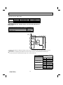
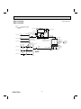
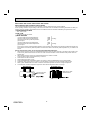
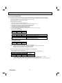
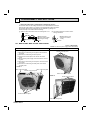
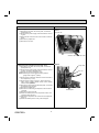
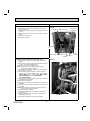
3. Removing the fan motor
(1) Remove the top panel, the service panel, and the front
panel (Refer to 1).
(2) Disconnect the power supply and indoor/outdoor connecting wire.
(3) Disconnect the connector CNF1 on the outdoor control P.C.
board.
(4) Remove the propeller fan.
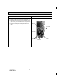
(5) Remove the fan motor.
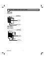
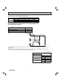
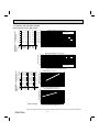
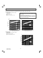
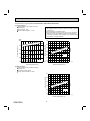
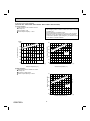
Photo 7
Propeller fan
Screws of the outdoor fan motor
Photo 8
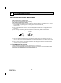
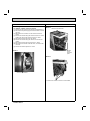
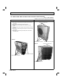
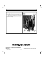
4. Removing the compressor and 4-way valve
4-way valve
(1) Remove the top panel, the service panel, and the front
panel (Refer to 1).
(2) Disconnect the power supply and indoor/outdoor connecting wire, and remove the back panel.
(3) Recover gas from the refrigerant circuit.
NOTE: Recover gas from the pipes until the pressure
gauge shows 0 kg/cm2 (0 MPa).
(4) Disconnect the compressor lead wire from the terminal of
the compressor (U, V, W).
(5) Disconnect the outdoor control P.C. board connectors:
CNF1, CNTH1, CNTH2, CN63H, CN712, CN791, CN792,
CN793, CN794 (MXZ-4C)
(6) Remove the screws fixing the electrical parts, and remove
the electrical parts (Photo 4).
(7) Remove the propeller fan.
(8) Remove the screws fixing the separator, and remove the
separator.
(9) Remove the sound proof felt.
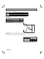
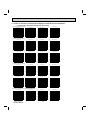
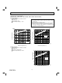
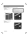
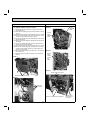
(10) Detach the brazed parts of the compressor suction and
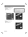
discharge pipes (Photo 9).
(11) Remove the compressor nuts and remove the compressor
(Photo 9).
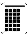
(12) Detach the brazed parts of 4-way valve and pipes.
OBH702A
79
R.V. coil
Brazed parts