1
Contents
Figures
Figure 1:
Figure 2:
Figure 3:
Figure 4:
Figure 5:
Figure 6:
Figure 7:
Figure 8:
Figure 9:
Figure 10:
Figure 11:
Figure 12:
Figure 13:
Figure 14:
Figure 15:
Figure 16:
Figure 17:
Figure 18:
Figure 19:
Figure 20:
Figure 21:
Figure 22:
Figure 23:
Figure 24:
Figure 25:
Figure 26:
Figure 27:
Figure 28:
Figure 29:
Figure 30:
Figure 31:
Figure 32:
Figure 33:
Figure 34:
Figure 35:
Figure 36:
Figure 37:
Figure 38:
Figure 39:
Figure 40:
Figure 41:
Figure 42:
Warmflo Model FW-538
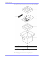
Filter and Filter Mount ........................................................................3
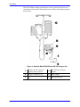
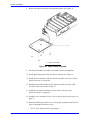
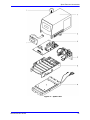
WF-250 Heat Exchanger Cassette.....................................................4
Warmflo FW-538 ................................................................................5
Warmflo Model FW-538 with WF-250 Surgery Set ............................6
Setup for Output Temperature Check ..............................................11
Setup for Over-Temperature Alarm Function Check ........................14
Accessing Heater Plates ..................................................................27
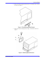
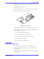
Filter Mounting Bracket Removal .....................................................31
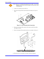
IV Mounting Bracket Removal..........................................................31
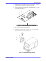
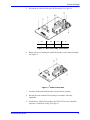
Cover Assembly Cable Connections ................................................32
Display PCB Assembly Removal .....................................................32
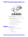
Cover Assembly Cable Connections ................................................33
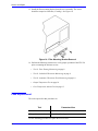
IV Mounting Bracket Removal..........................................................33
Filter Mounting Bracket Removal .....................................................34
Fuse Location...................................................................................35
Main PCB Cable Connections..........................................................37
Main PCB Screws ............................................................................37
Main PCB Cable Connections..........................................................38
Cover Assembly Cable Connections ................................................39
Display Assembly Screws ................................................................40
Cover Assembly Cable Connections ................................................40
Rear Panel Cable Connections ........................................................43
Rear Panel .......................................................................................43
Rear Panel Screws...........................................................................43
Rear Panel Ground ..........................................................................44
Equipotential Terminal Wiring ..........................................................44
Rear Panel Assembly Connection....................................................45
Rear Panel Assembly Cable Connections .......................................45
Door Assembly Cable Connections..................................................47
Door Assembly Pin...........................................................................47
Door Assembly Cable Retainer ........................................................48
Door Assembly Cable Routing .........................................................48
Cable Retainer Placement ...............................................................49
Door Assembly Pin Installation.........................................................49
Door Assembly Cable Connections..................................................50
Upper Heater Assembly ...................................................................52
Spare Parts ......................................................................................65
Packing.............................................................................................68
Increasing/Decreasing Temperature ................................................74
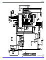
Main Control Board Schematic Diagram (Sheet 1 of 2) ...................77
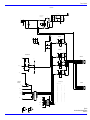
Main Control Board Schematic Diagram (Sheet 2 of 2) ...................79
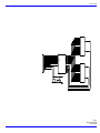
Display Printed Circuit Board Schematic Diagram ...........................81
iii