1
RM2042
3
SERVICE
3.1 MAINTENANCE
PREVENTIVE MAINTENANCE
If the VHF DSC RM2042 has been installed in a proper way the maintenance can, dependent on the
environments and working hours, be reduced to a performance check at the service workshop at intervals,
not exceeding 12 months. A complete performance check list is enclosed in this manual, chapter 3.5
PERFORMANCE CHECK.
Inspection of the antenna, cables, and plugs for mechanical defects, salt deposits, corrosion, and any
foreign bodies shall be done at regular intervals not exceeding 12 months.
Along with each RM2042 a test sheet is delivered in which all the measurements, made in the test
department of the factory, are listed. If the control measurings made in the service workshop should not
show the same values as those listed in the test sheet, the set must be adjusted as specified in
chapter 3.6. ADJUSTMENT PROCEDURE.
CHANGE OF BATTERY FOR BACK-UP
The RM2042 is constructed with a real time clock, which uses a lithium battery for power back-up. By
means of this battery, it is possible to maintain track of time and date even though the RM2042 has been
turned off.
The capacitance of the battery is 180 mAh (milli Ampere hours) and as the real time clock only consumes
a current of about 7µA, the battery should last for a period of at least 2.5 years. However, in practice this
period will be longer, because the battery is only used when the RM2042 is turned off.
The battery is located at the microprocessor (module 2) and is soldered to the PCB to obtain mechanical
stability.
The battery can be ordered from S.P. Radio, Denmark by using the spare part number 47.004.
IMPORTEN! The old battery shall be handed over to the authorities for proper destruction, to avoid
damages of the enviromental by the lithium.
CHANGE OF SOFTWARE
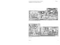
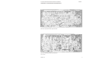
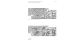
The microprocessor (module 2) includes the two PROM’s U3 and U5, which contain the software. To
locate these PROM’s please see the photo of the microprocessor module given in section 4 in this manual.
NOTE! If the software has to be changed, it is always necessary to change both PROM’s at a time.
3.2 ALIGNMENT INSTRUCTIONS
INTRODUCTION
The measuring values indicated in chapter 5. CIRCUIT DESCRIPTION AND SCHEMATIC DIAGRAMS
are typical values and as indicated it will be necessary to use instruments in absolute conformity with the
list given on the next page.
9403
PAGE 3-1