1
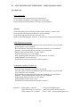
Tools Required:
a.
b.
c.
d.
e.
f.
g.
h.
i.
j.
k.
l.
m.
5
16ft. Measuring Tape
Chalk Line
Rotary Hammer Drill
3/4” diameter Masonry Drill Bit
Hammer
SAE Wrenches and Ratchet Set
2ft. Level
4ft. Level
Crow Bar
12ft. Step Ladder
Side Cutters
Screwdrivers
4” x 4” Wooden Blocks (for unpacking)
INSTALLATION INSTRUCTIONS
When the lift arrives on site:
• Read the owner’s manual and make sure the installation instructions are fully
understood.
• Check for any freight damages.
• Check the contents of the accessory and hardware boxes to make sure no parts are
missing.
• Gather all the tools listed above.
5.1
UNPACKING PROCEDURE
1.
Important! Place the main structural components on wooden blocks so that the
steel shipping frames can be removed.
2.
Remove the plastic wrapping.
3.
Remove the crossmember, and the actuator bar.
4.
Unbolt the steel shipping frames.
5.
Lay each tower on the floor with the carriage side up.
6.
Check the installation area for obstructions. (Lights, Heating Ducts, Ceiling, Floor
Drains, etc.)
7.
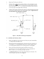
Prepare the bay by selecting the location of the lift relative to the walls. Clear the
installation area of all packaging materials to avoid trip hazards. Draw a chalk
line on the floor to represent the centerline of the bay then draw a second chalk
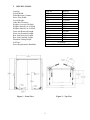
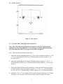
line at 90° for locating the lift towers. Refer to Figure 3.
4