1
BRAKES
PL
5 - 59
DISASSEMBLY AND ASSEMBLY (Continued)
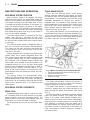
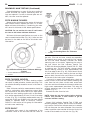
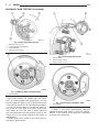
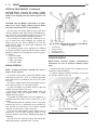
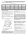
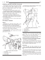
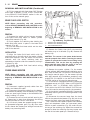
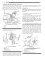
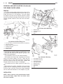
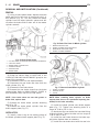
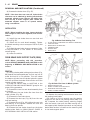
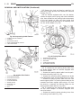
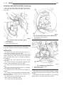
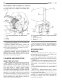
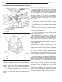
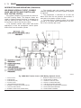
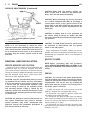
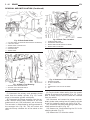
(4) Install piston into caliper bore pushing it past
the piston seal until it bottoms in the caliper bore
(Fig. 122).
Fig. 122 Installing Piston Into Caliper Bore
1 – BOOT
2 – PISTON
3 – CALIPER
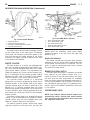
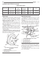
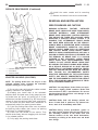
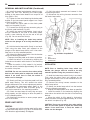
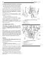
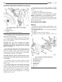
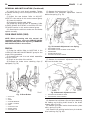
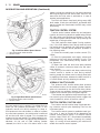
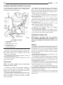
(5) Position the dust boot into the counterbore of
the caliper assembly piston bore.
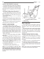
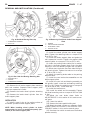
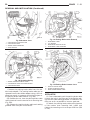
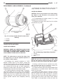
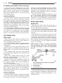
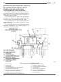
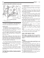
(6) Using a hammer and Installer, Special Tool
C-4689, and Handle, Special Tool C-4171, drive the
boot into the counterbore of the caliper (Fig. 123).
(7) Install the brake shoes.
(8) Reinstall the caliper on the vehicle and bleed
the brakes as necessary. Follow the installation procedure found in DISC BRAKE CALIPER in the
REMOVAL AND INSTALLATION section in this section of this service manual group.
CLEANING AND INSPECTION
BRAKE TUBES AND HOSES
Flexible rubber hose is used at both front and rear
brakes. Inspection of brake hoses should be performed whenever the brake system is serviced and
every 7,500 miles or 12 months, whichever comes
first (every engine oil change). Inspect hydraulic
brake hoses for severe surface cracking, scuffing,
worn spots or physical damage. If the fabric casing of
the rubber hose becomes exposed due to cracks or
abrasions in the rubber hose cover, the hose should
be replaced immediately. Eventual deterioration of
the hose can take place with possible burst failure.
Faulty installation can cause twisting, resulting in
wheel, tire, or chassis interference.
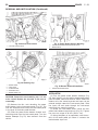
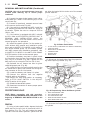
Fig. 123 Installing Dust Boot In Caliper Counterbore
1
2
3
4
–
–
–
–
HAMMER
SPECIAL TOOL C-4171
SPECIAL TOOL C-4689
CALIPER
The steel brake tubing should be inspected periodically for evidence of corrosion, physical damage or
contact with moving or hot components of the vehicle.
DISC BRAKES (FRONT)
BRAKE SHOES
Clean the front brake shoes and calipers with a
water-dampened cloth or with a brake cleaner. Do
not use a petroleum based product.
If a visual inspection does not adequately determine the condition of the lining, a physical check will
be necessary.
Remove the front disc brake shoes. Refer to DISC
BRAKE SHOES in the REMOVAL AND INSTALLATION section in this section of this service manual
group.
The combined brake shoe and lining material
thickness should be measured at the thinnest part of
the assembly.
When a set of brake shoes are worn to a total
thickness of approximately 7.95 mm (5/16 inch) or
less, they should be replaced.
Replace both brake shoe assemblies (inboard and
outboard). It is necessary that both front wheel sets
be replaced whenever brake shoe assemblies on
either side are replaced.