1
Section 4.0 - APPLICATION AND INSTALLATION
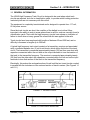
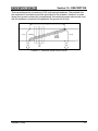
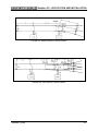
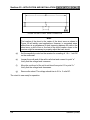
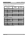
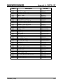
FIGURE 4-6. OVERLAPPED CIRCUITS
4.3 EQUIPMENT MOUNTING DATA
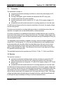
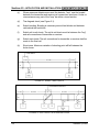
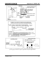
A transmitter or receiver basic housing consists of a cast iron box, M374986, with cover
M347723, and a pedestal, M224650, which are shipped separately. The unit is mounted
near the rails with the pedestal buried in the ground, so that the bottom of the box is
two to four inches above the ground. The length of the track lead to the nearest rail shall
be no longer than three feet (see Figure 4-7).
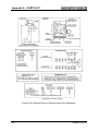
The 117 volt, 60 Hz power lead and the relay control wires are brought through a
special opening in the pedestal and through the bottom of the box. The track leads are
brought through the end of the box nearest the rails. The terminals on the AAR terminal
strip are identified for convenience in wiring all external connections. A second soldertype terminal strip is provided to mount the tuning capacitors required to resonate that
section of track between the track lead connections and the rail-to-rail short.
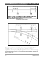
FIGURE 4-7. MOUNTING EQUIPMENT
SM5865 (12/99)
4-5