1
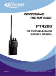
PROFESSIONAL
TWO-WAY RADIO
PT5200
FM PORTABLE RADIO
SERVICE MANUAL
V070607
PDF created with pdfFactory Pro trial version www.pdffactory.com
PT5200 SERVICE MANUAL
DANGEROUS!!
CONTENTS
Do not connect the AC power or DC power over 8.6V with
any connector or terminals of the radio. Otherwise it will
cause fire, electric shock or damage to the radio.
WARNING
Do not reverse power connection.
It may cause harm to the radio if signal input on the
antenna connector is bigger than 20 dBm (100mW).
Chapter 1 Introduction..........................................................2
Chapter 2
Chapter 3
Chapter 4
Chapter 5
Radio Overview and Function Keys.....................2
Electrocircuit ........................................................3
Function Description and Parameter Setting .......8
Service Assemble and Disassemble .................10
Chapter 6
Chapter 7
Chapter 8
Chapter 9
Radio Debugging ...............................................13
Technical Specifications.....................................15
Trouble Shooting................................................15
KBC-42A Charger..............................................16
Appendix 1 Abbreviations...................................................16
Appendix 2 Electronic Component List...............................16
Do not turn on the power before the antenna or load
connection is completed.
Appendix 3 Framework Component List.............................17
Appendix 4 Accessory List..................................................21
If the antenna has been damaged, do not use the radio.
Damaged antenna may cause lightly burning on skin.
Figure1 PT5200 Top Board Position Mark Diagram..........22
Though the radio is waterproof, it's better to avoid putting
it in rain or snow, or any other liquid to ensure its life and
performance.
Figure2 PT5200 Bottom Board Position Mark Diagram.....23
Figure 3 PT5200 Schematic Circuit Pane Diagram............24
Figure 4 PT5200 Schematic Circuit Pane Diagram............25
Figure 5 KBC-42A Schematic Circuit Diagram ...................26
STATEMENT
Kirisun Electronic (Shenzhen) Co., Ltd owns the copyright
of KSP5200 software.
Unauthorized Duplication of KSP5200 software is strictly
prohibited.
Kirisun Electronic (Shenzhen) Co., Ltd owns the copyright
of the MCU software.
Kirisun Electronic (Shenzhen) Co., Ltd owns the copyright
of the radio outward/structure/circuit design.
Kirisun Electronic (Shenzhen) Co., Ltd owns the copyright
of this service manual. Unauthorized
publication is
prohibited.
Kirisun Electronic (Shenzhen) Co., Ltd owns the
trademarks “KIRISUN”, “
”,“ 科立讯” .
1
PDF created with pdfFactory Pro trial version www.pdffactory.com
PT5200 SERVICE MANUAL
Chapter 1 Introduction
1.1 Introduction
This manual applies to the service and maintenance of PT5200
series of FM portable radios, and is designed for the engineers and
professional technicians that have been trained by Kirisun. In this
manual you can find all the information of product service. Kirisun
reserves the rights to modify the product structure and specification
without notice in order to enhance product performance and quality.
You can also log on our website www.kirisun.com to download the
latest service manual or contact your local dealer or us.
Read this manual before repairing the product.
1.2 Service Precautions
Safety
Avoid skin contacting with the antenna connector and PCB.
Do not reverse the power polarities.
If signal input at antenna connector is bigger than 20dBm(100mW),
it may cause damage to the radio.
Do not turn on the power before the antenna and load connection is
completed.
Do not use the radio if the antenna has been damaged. Contacting
the damaged antenna will cause slightly burning on the skin.
1.3 Service
All the Kirisun products are subject to the service warranty.
The main unit of the radio is guaranteed for free service of 12
months. Accessories (such as battery pack, power adapter, antenna
or charger) are guaranteed for free service of 6 months. Earphones
are wearing parts and out of warranty.
In one of the following situations, charge free service will not be
available.
No valid service warranty or original invoice.
Malfunction caused by disassembling, repairing or reconstructing
the radio by the users without permission.
Wearing and tearing or any man-made damage such as mechanical
damage, burning or water leaking.
Product serial number has been damaged or the product trademark
is difficult to identify.
After the warranty expires, lifetime service is still available. And we
also provide service components to service stations and service
staff.
Chapter 2 Radio Overview and Function Keys
2.1 Radio Overview
Electromagnetism Interference
It's prohibited to use or repair the radio in the following places:
Hospital, health center, air port
Any area with a potentially explosive atmosphere (where the air
contains gas, dust and smog, etc.), such as the storage or
transportation facilities of fuel or chemicals.
Any area of dynamite or exploder.
It's recommended to avoid using or repairing the radio in the
following places:
It's recommended to avoid using the radio in a car that is moving.
The radio wave might interfere the auto engine and cause it to stop
working.
2
7
1
3
5
4
8
6
Figure2-1
Component Replacement
All the components used in repair service should be supplied by
Kirisun.
Other components of the same models available on the market are
not surely able to use in this product and we do not guarantee the
quality of the product using such components.
Please fill in a component application forms if you want to apply for
any components from Kirisun.
The following is one sample form that might be used to apply for
any components from Kirisun.
Component Application
① LED Indicator
Lights red while transmitting signals; lights green while receiving
signals.
Flashes red while in low battery power during transmitting.
② Channel Selector
Rotate it to select channel 1-16.
③ Power/Volume Switch
Turn clockwise till a click is heard to switch on the radio.
Turn counterclockwise till a click is heard to switch off the radio.
Rotate it to adjust the volume after turning on the radio.
④ PTT (Push-to-talk)
To make a call, press and hold the PTT button, then speak into the
Radio
Model
PT5200-01
PT5200-01
Compo
nent
N o.
FET
Q104
Triode Q101
Model/
Specifications
Material Serial
No.
RD07MVS1
2SC5108(Y)
105-RD07MV-001
104-SC5108-001
Qua
ntity
1
1
microphone in normal voice.
Release the PTT button to receive a call.
⑤ Side key 1
Pro gramm able funct ion button: Pres s it t o act ivate the
programmable auxiliary function.
⑥ Side key 2
Pro gramm able funct ion button: Pres s it t o act ivate the
programmable auxiliary function.
2
PDF created with pdfFactory Pro trial version www.pdffactory.com
PT5200 SERVICE MANUAL
⑦ Top Button
Pro grammable funct ion button: Press it to activate the
programmable auxiliary function.
IF Circuit
The 1st IF signals from the crystal filter are amplified at the first IF
⑧ Microphone/Speaker Jacks
For connecting the optional Microphone/Speaker.
amplifier (Q204), and then are sent to the IF processing IC (IC204,
TA31136FN).
The IF IC consists of the 2nd frequency mixer, the 2nd local
oscillator, IF amplifier, limiter, phase frequency detector, and noise
Chapter 3 Electrocircuit
3.1 Frequency Configuration
amplifier.
After amplifying TCXO (X301), the 4th harmonic 51.2MHz is made
as the signal source of the 2nd local oscillation. The 2nd oscillation
signal( 51.2MHz ) and the 1st IF signal( 51.65MHz) are mixed at
IC204 to generate 2nd IF( 450kHz ) . After the 2nd IF signal is
amplified and its amplitude is limited at IC204, and then filtered at
porcelain filter (wide band CF201/ narrow band CF202, 450kHz),
IC204 demodulates and sends out audio signals.
Figure 3.3 Frequency Configuration
This radio adopts the 2nd Mixer, the 1st IF 51.65MHz, the 2nd IF
450kHz.
The receiver's first local oscillation is generated by the frequency
synthesizer. The second local oscillation adopts the 4th harmonic
51.2MHZ of TCXO.
The transmitter signals are generated by frequency synthesizer.
The reference frequency of frequency synthesizer is generated by
TCXO.
3.2 Receiver (RX)
Figure 3.5 IF System
Receiver Audio Signal Processing
IC404, IC405, IC407 , and IC408 and their peripheral circuit
compose the receiver audio signal processing circuit. IC204 sends
audio signals to IC404 for amplification, and then one route goes to
IC405 (CTCSS signaling filtering circuit) for waveform shaping and
then to IC6-D; one route goes to IC408 where the signals are
amplified, de-emphasized, filtered and the HF (high frequency) and
LF (low frequency) will be eliminated, and then for the remaining
300-3000Hz audio, one route is sent to volume potentiometer for
adjustment and finally sent to the audio amplifier (IC401), and the
other one route passes IC407 (2-Tone/5-Tone filter ) to MCU.
Figure 3.4 Receiver (RX)
The Receiver Front Terminal
Signals from the antenna pass through the RX/TX switch (D102,
D103, D104); and then undesirable out-of-band signals will be
filtered out at the band pass filter (BPF) consisting of C260, L756,
L732, C259, C750,C731,D700,C730,L212,C256, C257 , D210,
C255, L211, C253, and D209; then signals are amplified at the
low noise amplifier (LNA) consisting of Q26 and its peripheral
components.
The output from the LNA passes the BPF consisting of L207,
L206, L720, C248, C702, D207, C245 , C244, and C733 for
filtering and then is sent to the first grade frequency mixer (Q21).
The First Frequency Mixer
After mixing the receiving signals from LNA with the first local
oscillation signals from the frequency synthesizer, the 1st IF signals
( 51.65MHz) are generated. The first IF signals pass the crystal
filter (XF203), which will filter the signals of adjacent channel and
those out of band.
Figure 3.6 Receiver Audio Signal Processing
Squelch Circuit
Demodulation output from IC204 is sent to the selection frequency
noise amplifier, which consists of IC204 inner noise amplifier and
C121, R252, R211, C209, and R212 to be filtered off the noise.
After being amplified at Q205, noise is sent to D299 for wave
checking and then sent to MCU, which determines the noise
volume to control the squelch.
Audio Amplifier
IC401 and its peripheral components construct the BTL audio
amplifier.
Receiving audio signals, voice indication signals, indication tone
signals and warning tone signals are collected for audio
amplification to drive the speaker. Warning tone has no volume
3
PDF created with pdfFactory Pro trial version www.pdffactory.com
PT5200 SERVICE MANUAL
control.
transmitter output power will decrease. Vice versa, such can ensure
Speaker Impedance: 16Ω
Q405: Receiving Audio Signal Switch
steady transmitter output power in different working circumstances.
MCU changes the input power to IC3B to set the power.
Notice: Any terminal of the speaker cannot be connected with the
ground!
Transmitter Audio Signal Processing
CTCSS Signal Filtering
The IC204 demodulated output audio signals may contain CTCSS
(continuous tone coded squelch system) and DCS (digital coded
squelch). The frequency spectrum of CTCSS/DCS is 2-250Hz. The
filtering circuit constructed by IC405 can filter out the signals out of
the CTCSS/DCS frequency spectrum to ensure MCU to decode
CTCSS/DCS more precisely.
Figure 3.9 Transmitter Audio Circuit
3.3 Transmitter (TX)
Transmitter Power Amplifier
Figure 3.7 Power Amplifier and Antenna Switch Diagram
IC402 and IC408 and their peripherals components construct the
transmitter audio processing circuit. After the audio signals from
MIC are amplified, one route is sent for demodulation (VOX signals)
and then sent to MCU; the other one route passes AGG circuit to
IC408, where the amplitude of signals is limited, and signals are
filtered and amplified, and then are sent together with CTCSS/DCS
to VCO for modulation.
J2 is the external MIC socket. When the external MIC is in use, the
inner MIC will be cut off automatically, but inner PTT will remain
activated.
The modulated RF signals from VCO are amplified at Q101, Q102,
and Q103 and then are sent to Q104 for amplification. Q104 output
power: 4.5W.
3.4 Frequency Synthesizer
The Q103 and Q104 gate offset is controlled by APC circuit.
Changing gate-offset voltage can control the transmitter output
power conveniently.
APC (Auto Power Control)
Figure 3.10 Frequency Synthesizer
Figure 3.8 APC Circuit
R167, R168, and R169 are the amplifier current checker; IC101A is
the sample amplifier of the amplification current; IC101B is the
power comparison amplifier.
If the transmitter output power is too large, the amplifier current will
increase, IC101A output will mount, IC101B output voltage
decrease, the offset voltage added to Q103 and Q104 will decrease,
and then the transmitter output power will decrease. Vice versa,
such can ensure steady transmitter output power in different
working circumstances.
MCU changes the input power to IC101B to set the power.
Transmitter Audio Signal Processing
R167, R168, and R169 are the amplifier current checker; IC3A is
the sample amplifier of the amplification current; IC3B is the power
comparison amplifier.
If the transmitter output power is too big, the amplifier current will
increase, IC3A output will mount, IC3B output voltage decrease, the
offset voltage added to Q11 and Q12 will decrease, and then the
The radio adopts PLL (Phase Locked Loop) frequency synthesizer.
The frequency synthesizer consists of standard oscillator, voltage
controlled oscillator (VCO), programmable frequency demultiplier,
phase comparator, and low pass filter.
Q302, Q307, L304, L310 , D304, D302, D310, D308,
C309, C310, C308, C307, C322, C323, and C321 constitute
VCO.
IC3 01 (M B15E03SL) is P LL in tegrated ci rcuit, includ ing
programmable reference frequency demultiplier, programmable
swallowing frequency demultiplier, phase comparator, and charge
pump.
C326, R316, C328, C327, R317 , R318, and R319 construct
the low pass filter.
The standard frequency is supplied by X301 (TCXO, 13MHz).
The stan dard frequency from TCXO (Temperature Con trol
Transistor Oscillator) are demultiplied by the programmable
reference frequency demultiplier at IC301 to acquire 6kHz or
6.5kHz reference frequency (controlled by MCU according to the
preset channel frequency).
The oscillation frequency from VCO is sent to IC1, and demultiplied
by swallowing frequency demultiplier and compared with reference
frequency to acquire the error signals. Then pass the low pass filter
4
PDF created with pdfFactory Pro trial version www.pdffactory.com
PT5200 SERVICE MANUAL
and are sent to VCO to change VCO oscillation frequency to the
Checks the action of each function key
preset value, and then VCO is locked.
N=FVCO/FR
Generates content of voice indication
Generates Power-On Indication Tone
N: Frequency demultiplication times
FVCO :VCO oscillation frequency
Generates CTCSS/DCS signals
Generates 2-Tone/5-Tone signals
FR: Reference frequency
Generates power control signals
CTCSS/DCS decoding
Check Loss of Lock: When PLL is in loss of lock, IC pin14 sends out
low level signal to MCU, which controls the transmitter not to
transmit and initiate warning tome.
3.5 Voice Indication Circuit
The radio features voice indication, which is very useful at night or
in the environment of dim light.
MCU stores the voice indication of channels. If Channel
Annunciation function has been activated, every time you change
the channel, the speaker will sound voice annunciation of the
current channel number.
3.6 Power Supply
The radio is equipped with 7.4V, 1200mAh Li-Ion battery. The
battery supplies power directly to the transmitter amplifier circuit
(Q103, Q104) and the receiver amplifier (IC401). The power supply
of other circuits is the regulated 5V power.
IC502: 5V low voltage difference, micropower regulator, together
with Q10, and Q30 supply big current 5V power to the whole radio.
2-Tone/5-Tone decoding
Squelch check and control
Samplings VOX level
Controls audio processor to conduct audio emphasis/de-emphasis,
scrambler/descrambler, compander, filter and amplification.
2
Memorizer (E PROM, AT24C64)
Memorizes the radio channel data, CTCSS/DCS data, and other
data of function setting and parameter adjustment.
CTCSS/DCS Encoding and Decoding
CTCSS/DCS signals generated by MCU (output form pin20 and
pin26, PWM wave) are filtered at the filter circuit and then sent to
VCO and TCXO for modulation.
CTCSS/DCS signals from the receiver are sent to MCU for
demodulation. MCU determines whether the signals contain the
same CTCSS/DCS as that set on the radio and decides whether to
turn on the speaker.
Q502: T5V switch, controlled by MCU.
T5V: Supplies power for the front terminal of the transmitter.
Power Adjustment
MCU PIN2 sends DC signals to APC to control the transmitter
Q505: R5V switch, controlled by MCU.
R5V: Supplies power for the receiver RF amplification, mixing, IF
output power.
processing, audio signal processing.
Q503: C5V switch, controlled by MCU
C5V: The 5V power controlled by power saving supplies power for
the frequency synthesizer.
CTCSS
CTCSS (continuous tone control squelch system) is a squelch
control system modulated on carrier wave with continuous subaudio
frequency as pilot frequency. If a channel is set with CTCSS, only
when both the CTCSS of the receiver and that of the transmitter are
identical, communication is available, which avoids interference of
3.7 MCU
other signals.
39 groups of standard CTCSS frequency is available on the radio,
see Table 3.1.
CTCSS signals generated by MCU (PWM wave) pass the low pass
filter consisting of RC to be filtered off the high frequency over
300Hz and then are sent to VCO for modulation.
No.
Figure 3.11 MCU Diagram
MCU controls the working of each location of the radio to realize all
the radio functions.
Connects with the PC
Accesses the radio status data
Controls PLL to generate the receiving and transmitting local
oscillation frequency.
Accesses the current channel status.
Controls the LED status indication
Controls the power supply of each location
Frq [Hz]
No.
No.
Frq [Hz]
No.
1
67.0
11
Frq [Hz]
94.8
21
131.8
31
Frq[Hz]
186.2
2
69.3
12
97.4
22
136.5
32
192.8
3
71.9
13
100.0
23
141.3
33
203.5
4
74.4
14
103.5
24
146.2
34
210.7
5
77.0
15
107.2
25
151.4
35
218.1
6
79.7
16
110.9
26
156.7
36
225.7
7
82.5
17
114.8
27
162.2
37
233.6
8
85.4
18
118.8
28
167.9
38
241.8
9
88.5
19
123.0
29
173.8
39
250.3
10
91.5
20
127.3
30
179.9
5
PDF created with pdfFactory Pro trial version www.pdffactory.com
PT5200 SERVICE MANUAL
DCS
DCS (digital code squelch) is a kind of continuous digital code
modulated with voice signals on carrier wave to control squelch.
83 groups of standard codes (positive and inverse code) are
available. See table 3.2.
DCS signals generated by MCU (PWM wave shape) pass the low
pass filter to be filtered off the high frequency over 300Hz and then
are sent to VCO and TCXO for modulation. VCO modulates the
high frequency of DCS signals; TCXO modulates the low frequency
of DCS signals.
CTCSS/DCS signals from the receiver are sent to MCU for
modulation. MCU determines whether the DCS encoding of the
receiving signals is identical with that set on the radio and decides
whether to turn on the speaker.
Table 3.2
DCS Encoding List
023
114
174
315
445
631
025
115
205
331
464
632
026
116
223
343
465
654
031
125 226
346
466
662
032
131 243
351
503
664
043
132 244
364
506
703
047
134 245
365
516
712
051
143 251
371
532
723
054
152 261
411
546
731
065
155 263
412
565
732
071
156 265
413
606
734
072
162 271
423
612
743
073
165 306
431
624
754
074
172 311
432
627
3.9 Semiconductor Component
MCU Description
Table 3.3 Microprocessor (M30620FCPFP) Port Description
PIN Port Name I/O
TONEO
O
1
APC/TV
O
2
3
AFMUTE
O
4
5
SHIFT
SAVE
6
BYTE
O
O
I
7
8
9
10
11
12
13
14
15
16
17
18
CNVSS
XCIN
COUT
RESET
XOUT
GND
XIN
VCC
NMI
AFRDF
AFDT
TCLCK
I
I
O
I
O
I
I
I
I
I
O
I
Function
2T/5T output,warning tone output
TX power/ RX sensitivity adjustment
voltage output
RX audio mute control output, H: audio
output; L: mute
Frequency shift selection control
Control Power Save mode output
To select the width of the external data
bus, high level is 8-digit width.
working mode switching control
Backup clock input
Backup clock output
Reset input
Clock output
Ground
Clock input
Power positive polarity input
AK2346 RDF input
AK2346 TATA output
AK2346 MSK clock
19
20
21
22
23
24
25
26
27
28
29
30
31
32
33
CODIO
I/O
AK2346 DIO input
CTCOUT
PS
O
O
QT/DQT output
PLL power save mode control
NC
NC
NC
NC
NC
NC
NC
NC
NC
NC
NC
NC
CTC_PLL
TONE1
O
I
QT/DQT PLL modulation output
2T/5T input test
NC
TXD
NC
O
NC
Serial port output
RXD
CLK1
I
I
Serial port input
NC
RTSI
EECLK
O
I
NC
EEPROM clock wire
34
35
EEDAT
NC
O
NC
EEPROM data wire
NC
36
37
38
39
NC
NC
NC
NC
NC
NC
NC
NC
WE
NC
NC
NC
NC
NC
NC
NC
NC
NC
NC
O
O
O
EEPROMR/W I/O
NC
NC
W588C
NC
NC
NC
NC
NC
NC
NC
NC
MCU read & write control
NC
NC
NC
NC
NC
EEPROM read & write enable
NC
W588 audio chip control
SCLK588
ADA588
W588 clock
W58 data
BUSY588
NC
W58 test
NC
T/R
TX/RX VCO switching control. H: RX,
L:TX
40
41
42
43
44
45
46
47
48
49
50
51
52
53
54
55
56
57
58
59
60
61
62
63
64
65
66
67
68
69
70
71
72
73
74
75
NC
NC
NC
NC
I
NC
R5C
PLLUS
I
R5V voltage control. L:R5V output
Unlock check,H: Lock, L: Unlock
VCC
T5C
I
O
5V voltage input
T5V voltage control. L:T5V output
GND
MICMUTE
PLLDAT
PLLCLK
LE
TK
PTT
SK1
SK2
NC
NC
INT
NC
WCON
I
O
GND
MIC mute control。L: mute
O
O
PLL data output
PLL clock output
O
I
PLL enabling output
Key check
I
I
PTT check
Key check
Key check
NC
NC
Low voltage check
NC
Wide band RX control. H:effective in wide
band
6
PDF created with pdfFactory Pro trial version www.pdffactory.com
I
O
O
I
O
PT5200 SERVICE MANUAL
76
77
78
79
80
81
82
83
84
85
86
87
88
89
90
91
92
93
94
95
96
97
98
99
NCON
LEDR
LEDG
NC
NC
AFCO
I
O
O
I
O
O
AFSCK O
I
EN4
EN3
I
I
EN2
EN1
I
I
NC
NC
I
I
NC
TI
I
I
RSSI
BATT
I
I
VOX
GND
I
SQL
I
VCC
I
VCC
I
AFDIR O
APCSW O
100 DCSW
O
C5V switch
Q405
2SJ243
2SA1745
2SJ243
DTC144EE
Q404
2SK1824
Receiver audio output switch.
Narrow band RX control. H:effective in narrow
band
RX indicator control. H:Light
TX indicator control. H:Light
NC
Q503
NC
Audio powe r amplifier control. L: power
amplifier working
AK2346 data input/output clock
Channel encoding input (channel selection)
Channel encoding input (channel selection)
Channel encoding input (channel selection)
Channel encoding input (channel selection)
NC
NC
NC
CTCSS/DCS input
RX field strength signal input
Battery voltage check input
VOX voltage check input
GND
Squelch voltage check input
5V voltage input
5V voltage input
AK2346 data input/output control pin
TX power adjustment voltage input control
switch. H:Control is effective
TX power output control. L: TX power output
enabling
3.4 Semiconductor Function Description
Q502
Q504
T5V witch
R5V switch
Receiver audio output switch, cut off
when in emergency mode.
Table 3.5 Diode Function Description
Position
D102
D101
D103
D104
D201
D302
D304
D305
D310
D308
ZD101
D311
D306
D299
Type
MA77
HSC277
HSC277
HSC277
HSC277
MA2S376
MA2S376
MA360
MA2S376
MA2S376
HZU5ALL
MA2S111
MA2S111
1N4148
D508
D509
D505
D506
LED Red Transmitting indication
LED Green Receiving Indication
Function Description
Transmitter antenna switch diode
VCO output switch
Antenna switch
Antenna switch
VCO output switch
VCO oscillation variable capacitance diode
VCO oscillation variable capacitance diode
VCO modulation diode
VCO oscillation variable capacitance diode
VCO oscillation variable capacitance diode
APC output voltage-limiting diode
Loss of lock check diode
VCO power filtering accelerating diode
Noise demodulation
LED Red Transmitting indication
LED Green Receiving Indication
Table3.6: XF 203 Crystal Filter Features
Position Type
IC301 MB15E03SL
Function Description
Frequency synthesizer
Item
Nominal center frequency
IC101
Ic204
APC, voltage comparison, drive
Receiver's 2nd local oscillation, 2nd IF
Transmission bandwidth
40dB barrage bandwidth
a m pl i f i c a t i o n , a m p l i t u d e l i mi t ,
demodulation, noise amplification
Audio processing
MIC amplification
Pulse
Insertion loss
Guarantee attenuation
Terminal resistance
IC408
IC402
IC401
Ic9
NJM2904
Ta31136
AK2346
TC75W51FU
TDA2822D
AT2432NI
Receiver audio power amplifier
E2 PROM, memory channel frequency
da ta, f un ctio n set ti ng param eter,
debugging state parameters
IC10
IC505
Q101
Q102
Q304
Q111
Q306
Q205
Q10
Q104
Q103
Q107
Q21
Q26
Q204
Q507
Q06
Specified Value
51. 65MHz
±7.5kHz or bigger, within 3dB
±20.0kHz or smaller
1.0dB or smaller
3.0dB or smaller
80dB or bigger, within fo-910kHz
1.5kΩ/6PF
M30620FCPFP MCU
R3111N45IC
MCU reset circuit
2SC5108
Transmitter 1st amplification
2SC3356
Transmitter 2nd amplification
2SC5108
VCO buffering amplifier
2SC5108
VCO buffering amplifier
2SC4617
VCO power filter
Noise amplifier
2SC2412K
2SC1623
5V regulated output current stretcher
RD07MVS1
Transmitter final power amplifier
RD01MUS1
Transmitter power amplifier drive
DTA144EE
APC output switch
3SK318
The 1st frequency mixer
3SK318
Receiver HF amplifier
The 1st IF amplifier
2SC5108
DTC144EE
Red LED drive
Green LED drive
DTC144EE
Table 3.7 CF201 LTWC450F Features
Item
Nominal center frequency
6Db bandwidth
Specified Value
450kHz
±5.0kHz or bigger
50dB bandwidth
Pulse
±13.5kHz or smaller
3.0dB or smaller z
Insertion loss
Guarantee attenuation
7.0dB or smaller
45.0dB or bigger, f0±100kHz
Table 3.8 CF202 LTWC450G Features
Item
Nominal center frequency
6Db bandwidth
50dB bandwidth
Pulse
Insertion loss
Guarantee attenuation
Specified Value
450kHz
± 3.5kHz or bigger
± 12kHz or smaller
3.0dB or smaller
7.0dB or smaller
45.0dB or bigger, f0± 100kHz
7
PDF created with pdfFactory Pro trial version www.pdffactory.com
PT5200 SERVICE MANUAL
Figure 3.8
Semiconductor Component Packaging
automatically switch to the priority channel even the normal channel
is receiving signals at that time. And the radio will stay on the
Illustration:
2SC5108
M: MC
2SC3356
M: R24
B
2SC4617
B
E
E
FMMT591
B
E
E
E
RD01MUS1
RD07MVS1
D
E
E
G
S
RDA0002
S
D
G1
S
D
G2
D
Temporarily Delete” for 1 second to delete this channel temporarily
from the scanning list.
Note: The priority channel cannot be deleted. And when the number
of scanning channels is less than 2, you cannot delete any channel,
DA221
M: K
1
D
S
When scanning pauses on a channel,channel, press and hold the
button programmed as “Temporarily Delete ” or “ Scan +
G
2SK1824
Mark: B1
HT7150-1
d) Temporarily Delete
3SK318
M: YB-
S
C
G
S
C
E
2SK308NV
B
C
E
C
DTA144EE
B
C
B
C
DTC144EE
M:16
B
C
B
C
priority channel till that signal disappears. The dealer can set the
delay time between signal disappearing and continuing scanning.
2SC1623
M: L6
KTC4082
B
C
KTA1298
2SC4738
B
C
E
when the priority channel receives a signal the radio will
3
2
G
Chapter 4 Function Description and Parameter
Setting
4.1 Major Functions
4.1.1 16 Channels
The radio stores 16 channels.
4.1.2 Scan Channel (programmable by PC software)
a) Press the key designated as “ Scan” to activate scanning.
While in scanning, the radio checks every channel and stops on the
channel on which a signal is detected until that signal disappears. If
the delay time between signal disappearing and continuing
scanning has been preset, the radio will remain on that channel in
the delay time even receiving any signals at that time.
Only when there are two channels added in the scan list and the
scan function has been activated, the radio can start scanning.
b) The dealer can set the revert channel (transmitting channel) in
scanning among the following options:
1) Selected: The radio always reverts to the channel selected
before scanning when pressing PTT.
2) Selected + Talk Back: When the radio is in scanning, press the
PTT button and the radio will transmit signals on the selected
channel.
When the radio is in scanning pause, press the PTT button and the
radio will transmit signals on the current talk back channel.
3)Priority: When pressing PTT, the radio will transmit signals on
the priority channel in the scanning list.
4) Priority + Talk Back: When the radio is in scanning, press the
PTT button and the radio will transmit signals on the priority channel.
When the radio is in scanning pause, press the PTT button and the
radio will transmit signals on the current talk back channel.
5) Last Called: When pressing PTT button, the radio will transmit
from the last channel that received a call. If it has never received
any calls, it will revert to the first channel in the scanning list.
6) Last Used: When pressing PTT button during the scanning, the
radio will transmit from the last channel that you used to transmit. If
it has never made any calls, it will revert to the first channel in the
scanning list
c) Priority Scan
either.
After exiting scanning mode and entering it again, the temporarily
deleted channel will be added in the scanning list again.
4.1.3 CTCSS/DCS
CTCSS/DCS can realize selective calls and group calls. On the
same channel, only the two parties whose CTCSS/DCS are
identical can communicate. CTCSS/DCS signaling code on the
channel is preset.
4.1.4 TOT
The purpose of the time-out timer is to prevent any single person
from overlong using a channel to transmit and affecting the whole
group communication.
If the radio transmits longer than the preset TOT time limit, the radio
will stop transmitting and warning tone sounds. To stop the warning
tone, release the PTT button. Press the PTT again you can resume
transmitting.
TOT Pre-Alert:
You can set the time when the radio generates a "Pre-Alert tone",
before the TOT (Time Out Timer) expires. TOT will expire when the
selected time passes after a “ Pre-Alert Tone”.
TOT Rekey Time:
TOT Rekey-Time sets the "penalty" time in which the radio cannot
be re-keyed for transmitting after the Time Out Timer setting is
exceeded. During the Rekey time, if you press PTT, warning tone
sounds and transmission is prohibited.
TOT Reset Time:
TOT Reset Time sets the minimum "wait" time allowed between
transmissions that will reset the Time Out Timer. After setting this,
TOT continues even after PTT is released unless the TOT Reset
Timer has expired.
4.1.5 Auto Power Save
When no signals are being received or no operations are being
conducted for over 10 seconds, the battery power saving will be
activated to reduce power consumption. When it is receiving signals
or in operating state, battery power saving is inactive.
Power Save Type: 1:1, 1:2, 1:4, and OFF.
4.1.6 Low Battery Warning
When the battery power appears low, the indicator flashes. If the
battery power is lower than the preset value during transmitting, the
status indicator flashes red. When the speaker sounds warning tone,
the radio will stop transmitting.
During scanning, if the priority channel has been set on the radio,
8
PDF created with pdfFactory Pro trial version www.pdffactory.com
PT5200 SERVICE MANUAL
4.1.7 Monitor
4.1.12 Squelch Level Selection
When no signals are being received, the radio squelch circuit mutes
the speaker.
The purpose of the squelch is to mute the speaker noise when no
signals are received or the signals are weak. When the squelch is
Press the MONI key to cut off the squelch control circuit, and you
will hear noise from speaker (no mater whether there are signals).
activated, you can hear noise from the speaker; when the squelch
is inactivated, you will not hear noise form the speaker. Selecting
Such operation is very useful when you want to adjust voice volume
or receive weak signals (to avoid voice intermittence when in weak
the squelch level is to select which the signal strength level is
strong enough to enable the squelch or weak enough to disable the
signals).
When you press the MONI key, the green indicator lights, and the
radio is in the state of monitoring.
squelch. Over high squelch level will make the radio unable to
receive signals efficiently when signals are weak; over low squelch
level will make the radio communication affected by noise or other
irrelevant signals. The squelch level has 0-9 options.
4.1.8 、 5-Tone Signaling
The dealer can activate or inactivate this function by programming.
5-Tone Signaling has 17 coding formats: CCIR1, CCIR2, PCCIR,
ZVEI1, ZVEI2, ZVEI3, PZVEI, DZVEI, PDZVEI, EEA, EURO
SIGNAL,NATEL, EIA, CCITT, MODAT, USER DEFINED1, and
USER DEFINED2. The last two are customized models.
1) 5-Tone Decoding
When receiving proper 5-tone signal, squelch will be activated
according to the “SP unmute” set by the user, and the radio can
receive the call and orange LED flashes.
The dealer can program the response way after decoding succeeds.
2) 5-Tone Encoding:
If the PTT ID on the channel you select has been set with 5-Tone, 5Tone signal will be transmitted when making a call.
Or transmit 5-Tone signal by pressing the PTT button and CALL1 or
4.1.13 Beep Tone
This option controls power on tone, channel busy tone and TOT
tone.
4.2 Parameter Setting (PC Mode)
The radio parameters have been programmed in the factory. The
user can program the radio parameters such as working frequency,
channels, CTCSS/DCS, auto scanning. We designed a user friendly
and convenient Chinese/English programming software KSP20 for
users to set parameters on the radio. The programming steps are
as follows:
A. Install the programming software KSP 5200 on the computer.
b. Connect the radio to the computer serial port with the specified
programming line (KSPL02). See Figure 4.1
CALL2 button, which can be set by the dealer.
4.1.9、 2-Tone Signaling
The dealer can activate or inactivate this function by programming.
PC
(RS232
Serial Port)
Programming
Radio
Line
(KSPL02)
(Speaker/ Mic
Socket)
1) 2-Tone Decoding
When receiving proper 2-Tone signal, squelch will be activated
according to the “SP unmute” set by the user, and the radio can
receive the call and orange LED flashes.
C. Turn on the computer power.
The dealer can program the response way after decoding succeeds.
2) 2-Tone Encoding:
D. Turn on the radio power.
E. Click the KSP5200 program to run the programming software.
If the PTT ID on the channel you select has been set with 2-Tone, 2Tone signal will be transmitted when making a call.
F. Click the “Program” in the KSP5200 pull-down menu, and click
“Read from Radio” to read the radio parameters into the
Or transmit 2-Tone signal by pressing the PTT button and CALL1 or
CALL2 button, which can be set by the dealer.
4.1.11、 Busy Channel Lockout
If “ busy channel lockout” has been activated, transmitting signals
is prohibited on the busy channel. If you press the PTT to transmit
on the busy channel, the speaker will sound busy channel lockout
tone, and you cannot transmit signals.
The dealer can set one of the following BCL types:
1) OFF: BCL is inactive and you can transmit on the busy channel.
2) Carrier wave: If carrier wave is detected, the radio is unable to
transmit.
3) CTCSS/DCS: The radio is allowed to transmit when the
computer; click “ Write to Radio” to transfer the PC programming
parameters into the radio.
G. You can program the following parameters with the KSP5200
software.
1)
The RX and TX frequency of each channel.
2)
The receiving and transmitting signaling of each channel.
3)
Busy channel lockout option.
4)
TOT
5)
Squelch level option.
6)
5-Tone
7)
2-Tone
8)
Power saving option.
9)
Beep tone option.
10) Monitor mode option.
11) Scan mode option.
12) Scan the revert channel option.
13) Scan the priority channel option.
CTCSS/DCS signalings are identical.
4) Selective signaling: The radio is allowed to transmit when the
For more details, please refer to the “ Help” in the KSP5200
software.
selective signalings (2-Tone or 5-Tone) are identical.
Notice:
1) Turn off the radio before connection.
2) When the radio is being read data, the indicator lights green and
4.1.10、 PC Programmable
You can program the radio functions and adjust some parameters
by PC programming software KSP5200.
Figure 4.1
9
PDF created with pdfFactory Pro trial version www.pdffactory.com
PT5200 SERVICE MANUAL
it's prohibited to press the PTT button; when the radio is being
written data, the indicator lights red.
3) Before the first time editing, you should read data form the radio
and backup the data.
4) If the radio cannot work normally after being written in with the
editing data, open the data backup and rewrite the backup into the
radio.
5) Model information is important radio data and is prohibited to
modify.
6) After programming, you need to turn on the radio power again to
make the radio resume the normal work.
4.3 Computer Test Mode:
Connect the radio to the radio communication port with the
specified programming line (KSPL02). See Figure 4.1.
Warning: Before entering the computer test mode, connect a HF
load of 50Ω to the radio antenna connector or connect the radio to a
comprehensive test device.
Under the computer test mode, you can modify the following
parameters with KSP5200 programming software:
1)
TX/RX low voltage
2)
High/Medium/Low power
3)
AK2346 VR 1/ 2 / 3 / 4
4)
DCS (DQT) balance
5)
6)
DCS (DQT) frequency deviation
CTCSS (QT) frequency deviation
7)
8)
DTMF frequency deviation
Tone frequency deviation
9)
10)
MSK frequency deviation
VOX gaining
11)
12)
Sensitivity
SQL 1/9(OPEN/SQUELCH)
Chapter 5 Service Assemble and Disassemble
The radio is precision communication equipment. Please be careful
when assemble or disassemble the radio during service.
5.1 Removing and Installing the Battery
To remove the battery, push the latch upwards and remove the
battery away from the radio. (See Figure 5.1)
Figure 5.1
To install the battery, match the tow bulges at the bottom of the
battery with the corresponding grooves at the radio aluminum alloy
frame and insert it in. Then press the upper end of the battery till
the latch secure. (See Figure 5.2 and 5.3)
4.4 Wired Clone (It can be prohibited by programming software)
When the wired clone function is activated, the radio can enter the
wired clone mode. After entering the wired clone mode, the radio
will not exit it automatically and you have to turn on the radio again
to enter the user's mode. Operating steps are as follows:
1) Turn on the radio with the MONI key pressed, and 2 seconds
later the red light flashes twice and two beep tones sound, and then
the radio enters the wired clone mode.
2) Press the PTT button on the host radio to activate/inactivate the
wired clone mode on the sub radio. But the wired clone mode of the
host radio will not be changed. When pressing the PTT button, the
green light flashing twice and one beep mean to activate the clone
mode on the sub radio; the red light flashing twice and two beeps
mean to inactivate the clone mode on the sub radio.
3) Press the MONI key, red light flashes, and it starts cloning. After
cloning is finished, the red light turns dim.
Figure 5.2
Figure 5.3
5.2 Removing and Installing the Belt Clip
To remove the belt clip, use your nail or a tool to lift the metal
spring piece in the belt clip from the topside, and then pull the belt
clip away from the radio.
To install the belt clip, match the upper head of the belt clip with the
glides on the rear of the battery, and then press the belt clip
downwards to lock it in place. (See Figure 5.4)
Note:
You can also activate/inactivate the wired clone mode by PC
programming software.
If the wired clone function has been prohibited, it cannot enter the
wired clone mode.
Cloning Line
Host Radio
Sub Radio
Figure 4.2
10
PDF created with pdfFactory Pro trial version www.pdffactory.com
Figure 5.4
PT5200 SERVICE MANUAL
5.4 Exploded View
5.3 Removing the Casing from the Chassis
1)
2)
Remove the knobs;
Remove the two knob nuts and the antenna nut;
3)
Remove the two cross head screws that fix the top cover at
the top;
4)
Remove the two cross head screws that fix the aluminum
alloy frame at the bottom;
5)
Pull the aluminum alloy frame out of the casing.
See Figure 5.5
No.
MATER I AL No .
DECRIP TION
201-00 0668 -R0 4
PTT COV ER BO ARD
1
2
201-000668-R05
PTT PLAS TIC KEYSTROKE
1
3
20 2-00 06 68 -R01
PTT KEYSTROKE
1
4
203-00 0558 -R0 4
SPEAK ER SPR IN G
2
LOGO LAB LE
1
1
5
Figure 5.5
5.4 Remove the Chassis from the Main Board
1)
Remove the screw of from the PCB;
2)
Melt the solder at the antenna point with an electric soldering
iron and take off the main board;
3)
Take away the two screws and the antenna connector.
See Figure 5.6.
Figure 5.6.
QTY
6
201-005200-R01
SURFA CE SHELL
1
7
121-100000-R07
SPEAKER
1
8
204-000558-R01
WAT ERPROOF WA SHER
2
1
9
20 1-0005 58-R0 9
LIGHT POLE
10
202-000558-R05
ANTENNA WATERPROOF WASHER
1
11
202-000558 -R0 4
SWITCH WATERPROOF WASHER
2
12
203-000558 -R0 1
ANT ENN A NUT
1
13
203-000558 -R0 2
SWITCH NUT
2
14
203-003208 -R0 9
KNOB RE TA INING RING
2
15
201-000668 -R0 3
ENCODE R KNOB
1
16
201-000668 -R0 2
VOLUME KNOB
1
17
202-000558 -R 03
ANNUNCIATOR KEYS TROK E
1
18
201-000558 -R0 8
ANNUNCIATOR KEYSTROK E STAKE
1
19
202-000558 -R0 1
MIC C O VER
20
204-006800-R06
MIC WASHER
1
3
21
202-000558 -R09
MIC UNDERLAY
1
22
301-20040G-R01
SCREW M2
10
PCB SUBAS SEMBLY
1
23
24
20 4-00 0558-R 0 4
20 4-00 3208-R 0 5
WA SHER
25
WA SHER
2
2
26
20 2-00 0558-R 0 6
WA SHER
1
27
20 1-00 0558-R 0 7
ANODE SHRAPNEL BRACKET
1
28
20 2-00 0558-R 0 8
ANODE CATHODE WASHER
2
29
20 3-00 3208-R 0 2
ANODE SHRAPNEL
1
30
30 2-17 040G -R0 1
SCREW M1.7
1
31
20 2-00 3208-R 0 7
INSULAT ING WAS HE R
1
32
20 2-00 0558-R 0 7
WATERPROOF WASHER
1
33
20 3-00 0558-R 0 7
ANTENNA HEAD
1
34
20 4-00 0558-R 0 5
ALNICO AEGIS PASTER
1
35
20 3-00 4200-R 0 1
ALNICO BRACKET
1
36
20 3-00 3208-R 0 4
CATHODE SHRAPNEL
1
37
20 1-00 0558-R 0 5
COPING
1
38
20 3-00 0558-R 0 5
PUSH FASTENER SP RING
1
1
39
20 1-00 0558-R 0 6
PUSH FASTENER
40
30 1-25 060J-R01
SCREW M2.5
2
41
20 4-00 0558-R 0 2
WATERPROOF WASHER
1
42
40 1-02 01C1-R06
ALNICO LA BLE
1
43
30 1-20 080G -R0 1
SCREW M2
2
44
20 4-00 0558-R 0 3
BUTTOM LABLE
1
11
PDF created with pdfFactory Pro trial version www.pdffactory.com
PT5200 SERVICE MANUAL
Figure 5.7 Exploded View
5. 6 Wearing Parts List
No. Material Serial No.
Name
QTY
111-030000-R03
Chip protective tube
FS01
110-220103-R12
Volume switch
K501
106-ED0873-R01
Channel/Encoder switch
K502
4
5
124-050000-R05
Earphone rod bearing
J401
124-050000-R04
MIC rod bearing
J402
6
604-052000-R01
PT5200 front cover components
1
7
202-000558-R01
PT558 earphone/Mic cover
1
8
9
202-000668-R01
PT668PTT rubber key
1
201-000668-R05
PT668PTT key
1
10
201-000668-R04
PT668PTT cover
1
11
604-006680-R02
PT668 Volume knob module
1
12
604-006680-R03
PT668Channel knob module
1
13
203-000558-R11
PT558 Antenna knob
1
14
203-000558-R02
PT558 Switch knob
2
1
2
3
15 204-003208-R05
PT3208
Potention meterention 2
meter washer
16
202-000558-R04
PT558 switch waterproof gasket
2
17
202-000558-R05
PT558 antenna waterproof gasket
1
18
203-000558-R07
PT558 antenna connector
1
PT5200 electrical material
1
19
20
202-000558-R09
PT558 MIC cover
1
21
301-20040G-R01
M2.0*4.0 Woven belly-tooth screw
10
2 2 604-005580-R04
PT558 Positive pole terminal module
1
23
24
301-20080G-R02
M2.0*8.0 Woven belly-tooth screw
2
604-005580-R05
PT558 Al alloy chassis
1
M2.5*5.0 Woven belly-tooth screw
2
26 604-005580-R06
PT558 Top cover module
1
27 202-000558-R07
PT558 Large waterproof gasket
1
25 301-25050J-R01
28
121-100000-R07
Speaker
1
29
201-000558-R08
PT558 Emergency Key Panel
1
30
201-000558-R09
PT558 Light guide lens
1
31
201-005200-R02
PT5200 Front cover
1
32
202-000558-R03
PT558 Emergency Key
1
33
204-000558-R01
PT558 Speaker waterproof net
1
34
204-006800-R06
PT6800 MIC gasket
3
35
201-000668-R03
PT668 Channel knob
1
36
203-003208-R09
PT3208 Knob retaining ring
1
37
201-000558-R07
PT558 P osit ive po le terminal
chassis
1
38
202-000558-R06
PT558 chassis waterproof gasket
1
39
202-000558-R08
PT558 Positive pole terminal gasket
1
40
203-003208-R02
PT558 Positive pole terminal
1
41
302-17040G-R01
Screw
1
42
202-000558-R08
PT558 P osit ive/N eg at ive pole
terminal gasket
1
43
203-003208-R04
PT3208 Negative pole terminal
1
44
203-004200-R01
PT4200 Al alloy chassis
1
45
204-000558-R02
PT558 waterproof spacer
1
46
204-000558-R03
PT558 Al alloy sticker
1
47
204-000558-R05
PT558 Al alloy spacer
1
48
301-20030G-R03
Screw
1
49
201-000558-R05
PT558 Top cover
1
50
202-000558-R14
PT558 Push fastener
1
51
203-000558-R05
PT558 Push fastener spring
1
12
PDF created with pdfFactory Pro trial version www.pdffactory.com
PT5200 SERVICE MANUAL
6.2 Debugging Items
Chapter 6 Radio Debugging
Before test/debugging, make sure all the equipments have been
well connected to the ground.
Before test/debugging, make sure the antenna output terminal has
been connected properly to the corresponding devices and load.
The transmitter output must pass RF power attenuator before being
connected to the standard signal source/ frequency deviator/
frequency spectrum.
When testing the receiver, make sure not to conduct transmitting
operation.
When in debugging/testing/service, make sure static free measures
for human body and equipments.
6.1 Service Equipment and Software.
The following equipments and software in Table 6.1 are necessary
for the service and test of the radio.
Table 6.1 For Test and Service: Equipment and Software
No. Item
1 Computer
2
3
4
5
6
7
Specifications
Higher than P2, compatible with IBM PC,
WINDOWS 98/ME/2000/XP
KSP-5200
Programming
Software
Programming Line KSPL02
Cloning Line
KCL01
DC Regulated
Output voltage:7.5V, Output current:≥ 5A
Power
RF power meter
Frequency Meter
Test range:0.5---10W
Frequency range: 100MHz500MHz
Impedance:50Ω
SWR ≤1.2
Frequency range: 0.1600MHz
Frequency
9
Deviator
Digital Multimeter
10 Audio Signal
Generator
11 RF power
Attenuator
12 Standard signal
source
13 Oscillograph
14 Audio voltmeter
Frequency precision: Higher than ± 1×10
Sensitivity: Higher than 100mV
Frequency range: DC600MHz
Test range:0--±5kHz
Input impedance: Higher than 10MΩ/V DC , with
the ability of testing voltage, current, impedance.
Frequency range: 2---3000Hz
Output level: 1---500mV
Attenuation:40dB or 50dB
Supporting power: Bigger than 10W
Frequency range: 10MHz---1000MHz
Output level:0.1uV~32mV (-127dBm~-17dBm)
Frequency range: DC~20MHz
Test range:10mV~20V
Test range:10mV~10V
The equipments in item 6, 7, 8, 10, 11, and 12 can be replaced by a
comprehensive test instrument.
PTT/RXD
5MS MIC
MICJACK
SP TXD GND
SPEAKERJACK
Figure 6.1 External Speaker/Mic Connector Definition
parameters can be modified (computer mode) with our KSP 5200
programming software. The modifiable parameters are as follows:
1)
2)
Frequency difference
TX power
3)
4)
5)
6)
7)
8)
9)
10)
11)
Low battery power warning threshold
Squelch level
CTCSS (QT) frequency deviation
DCS (DQT) frequency deviation
TX frequency deviation
DTMF frequency deviation
TONE frequency deviation
RX sensitivity
RX AF power
Debugging Procedures
a.
Enter the computer test mode. Access method refers to the
instruction in 4.2.1 parameter setting.
b.
Select the “Test Mode” option is KSP5200 program to
enter the computer test mode.
c.
Select the options that you want to adjust and adjust the
parameters on the computer.
d.
After adjustment, exit the computer test mode.
6.3 Debugging
6.3.1 TX Low Power Warning
Adjust the voltage to 6.6V.
In “ Test Mode” press “↓” to select “TX lower power” and
-6
8
During the course of maintenance, the radio needs to be tested and
debugged after replacing components. Some certain radio
press Enter key.
6.3.2 VCO Modification
Turn off the power saving mode. Set the RX frequency at the low
frequency (see Table 6.2). In receiving status, test the PD power
with the digital multimeter. Adjust the trimming capacitor TC302 to
make the PD power at 1V±0.1V. Set the RX frequency at the high
frequency, and PD power is 3.5V±0.1V.
Set the TX frequency at low frequency (see Table 6.2), press the
PTT button, test the PD power with the digital multimeter. Adjust the
trimming capacitor TC301 to make the PD power at 1V±0.1V. Set
the TX frequency at the high frequency, and PD power is 3.5V±
0.1V.
Table 6.2 Radio H/I/L Frequency
TX
Low Frequency
420.165MHz
Medium Frequency
445.165MHz
RX
420.165MHz
445.165MHz
High Frequency
469.965MHz
469.965MHz
6.3.3 PLL Frequency Adjustment
Under the computer test mode, press “ ↓”on the keyboard to
enter “Low Power (Low) ” and press Enter. Adjust VR1 to make
the TX frequency error at +/-200HZ.
6.3.4 TX Frequency Adjustment
Under the computer test mode, press “ ↓”on the keyboard to
enter “Low Power (Low) ” and press Enter. Press “←/→”key to
make the TX power at 0.5+/-0.1w and then press Enter to store the
setting. Use the same way to adjust “ Low Power (Medium), Low
Power (Medium High), Low Power (High)” at 0.5+/-0.1w.
13
PDF created with pdfFactory Pro trial version www.pdffactory.com
PT5200 SERVICE MANUAL
Deviation (Narrow Band)” and press Enter. Press “←/→”key to
Press “↓ ”on the keyboard to enter “Medium Power (Low)”
and press Enter. Press “←/→”key to make the TX power at 2+/-
make the DTMF Frequency Deviation at 1.5+/-0.1KHZ.
0.2w and then press Enter to store the setting. Use the same way to
adjust “Medium Power (Medium), Medium Power (Medium High),
6.3.9 TONE Frequency Deviation Adjustment
Under the computer test mode, press “↓”on the keyboard to
Medium Power (High)” at 2+/-0.2w.
Press “↓ ”on the keyboard to enter “High Power (Low)” and
enter “TONE Frequency Deviation (Wide Band)” and press Enter.
Press “← /→”key to make the TONE Frequency Deviation at 3+/-
press Enter. Press “← /→”key to make the TX power at 4+/-0.3w
and then press Enter to store the setting. Use the same way to
adjust “High Power (Medium), High Power (Medium High), High
Power (High)” at 4+/-0.3w.
0.3KHZ.
Press “↓ ”on the keyboard to enter “TONE Frequency
Deviation (Medium Band)” and press Enter. Press “←/→”key to
make the TONE Frequency Deviation at 2.3+/-0.2KHZ.
Press “↓ ”on the keyboard to enter “TONE Frequency
Deviation (Narrow Band)” and press Enter. Press “←/→”key to
make the TONE Frequency Deviation at 1.5+/-0.1KHZ.
6.3.5 Frequency Deviation Adjustment
Input 150mV, 1000Hz audio signals from the radio MIC, and press
“↓ ”to enter “ AK2346 VR2 Wide Band Low” and press Enter.
Press “← /→”key to make the maximum frequency deviation at
3.9+/-0.2KHZ.
Use the same way to make the maximum frequency deviation of “
AK2346 VR2 Wide Band Medium”, “ AK2346 VR2 Wide Band
High” at 3.9+/-0.2KHZ; “ AK2346 VR2 Medium Band Medium”
at 3.2+/-0.1KHZ; “AK2346 VR2 Narrow Band Medium” at 2.0+/0.2KHZ. (Notice: On the comprehensive test device, the audio
output level is 150mv and the filter is set to 50HZ~15K.)
6.3.10 VOX Gain Debugging
Under the computer test mode, press “↓”on the keyboard to
enter “VOX Gain 5 (Medium) ” (set the output level on the
comprehensive test device to 15mv) and press Enter to store the
data ----- do not press Enter until the numbers on the screen
become steady.
Press “↓ ”on the keyboard to enter “VOX Gain 1 (Medium)”
(set the output level on the comprehensive test device to 100mv)
and press Enter. Do not press Enter to store the data until the
numbers on the screen become steady.
6.3.6 DCS (DQT) TX Signal Wave Shape and Frequency
Adjustment
Under the computer test mode, press “↓”on the keyboard to
6.3.11 Receiver Sensitivity
Under the computer test mode, set the comprehensive test device
enter “DCS Frequency Deviation (Wide, Low)” and press Enter.
Press “← /→”key to make the DCS Frequency Deviation at
at the sate of testing pass band, and press “ ↓”on the keyboard
to enter “ Receiver Sensitivity (Low)” and press Enter. Press “←
0.85+/-0.15KHZ. Use the same way to adjust “DCS Frequency
Deviation (Wide, Medium)” “ DCS Frequency Deviation (Wide,
High)” at 0.80+/-0.10KHz; “DCS Frequency Deviation (Medium,
Medium)” at 0.6+/-0.1KHz; “DCS Frequency Deviation (Narrow,
/→” key to make the frequency waveform to the middle of the
whole waveform. Then press Enter to store the data. It's the same
to other 4 testing points (notice the corresponding frequency
change).
Medium)” at 0.4+/-0.1KHz. (Notice: The filter is set to
20HZ~300HZ.)
6.3.12 AK2346 Receiving Voice Debugging
6.3.7 CTCSS (QT) Frequency Deviation Adjustment
Under the computer test mode, set the RX frequency on the
comprehensive test device to the middle frequency among the 5
Under the computer test mode, press “↓”on the keyboard to
enter “CTC Frequency Deviation (67.0HZ ,Wide, Low)” and
press Enter. Press “← /→”key to make the CTC Frequency
Deviation at 0.80+/-0.10KHZ. Use the same way to adjust “CTC
Frequency Deviation (67.HZ ,Wide, Medium)”, “CTC Frequency
Deviation (67.HZ, Wide, High)” at 0.80+/-0.10KHZ; “CTC
Frequency Deviation (67.0HZ, Medium, Medium)” at 0.6+/-0.1KHZ;
“CTC Frequency Deviation (67.0HZ, Narrow, Medium)” at 0.4+/0.1KHZ; the test and specifications are the same for “CTC
Frequency Deviation (136.5HZ) and ”CTC Frequency Deviation
(254.1HZ). (Notice: The filter is set to 20HZ~300HZ.)
testing frequency points; signal strength at 1mv; AF voltage unit is
“W ”.
Press “↓ ”on the keyboard to enter “AK2346 VR3 (Wide Band,
Medium)” and press Enter. Press “←/→”key to make the AF
power to 0.4+/-0.05W. Set the AF power of “ AK2346 VR3 (Medium
Band, Medium)” and “ AK2346 VR3 (Narrow Band, Medium)” to
0.4+/-0.05W. (On the comprehensive test device, the AF deviation
is 3KHZ, 2.5KHZ, and 1.5KHZ separately.)
6.3.8 DTMF Frequency Deviation Adjustment
Under the computer test mode, press “↓”on the keyboard to
enter “DTMF Frequency Deviation (Wide Band)” and press Enter.
Press “← /→”key to make the DTMF Frequency Deviation at 3+/-
6.3.13 Receiver Squelch Setting
Under the computer test mode, press “↓”on the keyboard to
enter “SQL 1 ON (Wide Band, Low) ” (on the comprehensive test
device the RX frequency is low frequency, SIAND is adjusted to
10dB). Press Enter to watch the RX sensitivity and press Enter to
store the data after the value becomes steady. It's the same for
“SQL 1 ON (Wide Band, Medium Low)”, “ SQL 1 ON (Wide
Band, Medium)” , “SQL 1 ON (Wide Band, Medium High)”, and
0.3KHZ.
Press “↓ ”on the keyboard to enter “DTMF Frequency
“SQL 1 ON (Wide Band, High)”. (On the comprehensive test
device, the AF deviation is 3KHZ, 2.4KHZ, and 1.5KHZ separately.)
Deviation (Medium Band)” and press Enter. Press “←/→”key to
make the DTMF Frequency Deviation at 2.3+/-0.2KHZ.
Press “↓ ”on the keyboard to enter “DTMF Frequency
Press “↓ ”on the keyboard to enter “SQL 1 OFF (Wide Band,
Low)” (on the comprehensive test device the RX frequency is low
14
PDF created with pdfFactory Pro trial version www.pdffactory.com
PT5200 SERVICE MANUAL
frequency, SIAND is adjusted to 8dB. Press Enter to watch the RX
sensitivity and press Enter to store the data after the value
becomes steady. It's the same for “SQL 1 OFF (Wide Band,
Medium Low)”, “SQL 1 OFF (Wide Band, Medium)”, “SQL 1
OFF (Wide Band, Medium High)”, and “SQL 1 OFF (Wide Band,
High)”.
Press “↓ ”on the keyboard to enter “SQL 9 ON (Wide Band,
Low)” (on the comprehensive test device the RX frequency is low
frequency, SIAND is adjusted to -117dB). Press Enter to watch the
RX sensitivity and press Enter to store the data after the value
becomes steady. It's the same for “SQL 9 ON (Wide Band,
Medium Low)”, “SQL 9 ON (Wide Band, Medium)”, “ SQL 9
ON (Wide Band, Medium High)”, “SQL 9 ON (Wide Band,
High)”, “ SQL 9 OFF (Medium Band, Medium)” and “ SQL 9
OFF (Narrow Band, Medium)”.
Press “↓ ”on the keyboard to enter “SQL 9 OFF (Wide Band,
Low)” (on the comprehensive test device the RX frequency is low
frequency, SIAND is adjusted to -119dB. Press Enter to watch the
RX sensitivity and press Enter to store the data after the value
becomes steady. It's the same for “SQL 9 OFF (Wide Band,
Medium Low)”, “SQL 9 OFF (Wide Band, Medium”, “SQL 9
OFF (Wide Band, Medium High)”, “SQL 9 OFF (Wide Band,
7.3 Transmitter
RF Power
4.0W @7.5V DC
Frequency Stability
Maximum Modulation Frequency
Deviation
Modulation Sensitivity
≤ ± 2.5×10
±5kHz
Modulation Distortion( 300~3000Hz )
Adjacent Channel RF Power
Spurious and Harmonics
Residential Frequency
Modulation
Transmitting Current Sinking
≤ 3%
≤-70dB
≤ -70 dB
-6
15mV
≤ -45 dB
≤1.8A @ 7.5V DC
Chapter 8 Trouble Shooting
1
2
Battery power may be insufficient. Recharge or
No display after
switching on the change the battery pack.
The power switch is broken, and please change it.
radio.
The CPU is broken, and please change it.
The radio is remote killed and reprogram it.
The PLL crystal oscillator X301 is broken, and
PLL is unlocked.
(Beep
sounds)
High)”, “ SQL 9 OFF (Medium Band, Medium)” and “ SQL 9
OFF (Narrow Band, Medium)”.
please change it.
The oscillatingtube is broken, and please change
it.
The PLL chip IC301 is broken, and please change
it.
3
Chapter 7 Technical Specifications
7.1 General Specification
Frequency(MHz)
136~174MHz
400~450MHz
420 ~ 470MHz
Modulation
Number of Channels
Channel Spacing
16K0F3E
16
25 kHz( W),20 kHz (M),12.5 kHz(N)
1st MF: 51.65MHz 2nd MF:450kHz
7.5V negative grounding
470~512 MHz
350~390 MHz
MF
Working Voltage
Working Temperature -25℃~ +55℃
Antenna Impetance
50Ω
2kΩ
Mic Impedance
Model: KB-58L,Li-Ion Battery DC 8.4V , 1200mAh
Battery (Standard)
Dimension (WxHxD) 56 mm× 102 mm×29 mm
Weight
235g (With battery and antenna)
4
5
7.2 Receiver
≤ 0.28μV
Squelch Activation Sensitivity
Receiver Surplus Output
Modulation Receiving Bandwidth
Adjacent Channel Selectivity
≤ 0.25uV @ level 3 squelch
≤ -45dB
± 7kHz
≥ 70dB
≥ 65dB
≥ 70dB
Internal speaker:500mW, balance
@ distortion≤ 5%,16Ω
≤ 350mA
≤ 20mA
Intermediation Reject Ratio
Spurious Response Reject Ratio
Audio Output Power
Receiver Surplus Output
Modulation Receiving Bandwidth
Make sure the two communication radios are
using the channel of the same frequency.
Make sure the CTCSS/DCS tone is the same as
that of your group members.
Out of the effective communication range.
The antenna is not well connected, and please
Cannot receive screw the antenna again until secure.
HF amplifier Q26 is broken, and please change it.
signals.
The squelch level is too high and the squelch
cannot be activated. Reset the squelch level with a
computer.
Mixer tube Q21 is broken, and please change it.
MF processing chip IC408 is broken, and please
change it.
The power amplifier tube Q104 is broken and
6
Available Sensitivity (12dB SINAD)
Cannot talk to
or hear other
group
members.
7
there is no power output and please change it with a
The indicator
lights red when new tube.
The microphone is broken, and please change it
in transmitting
with a new one.
but no voice
The operational amplifier IC402 is broken, and
can be heard.
please change it with a new one.
The speaker is broken, and please change it with
The indicator
a new one.
lights green
The audio amplifier IC401 is broken and please
when in
receiving but no change it with a new one.
The switch tube Q404 and Q405 is broken, and
voice can be
pleas change it with a new one.
heard.
The operational amplifier IC408 is broken, and
Cannot
program the
radio
parameters
normally.
please change it with a new one.
Make sure the programming cable is well
connected.
The computer RS-232 serial port output is
unmoral, and please fix the computer.
The MIC is not well connected with the SPK
socket. Check the socket and if it is unable to work
normally please change it with a new one.
15
PDF created with pdfFactory Pro trial version www.pdffactory.com
PT5200 SERVICE MANUAL
Chapter 9 KBC-42A Charger
Appendix 1 Abbreviations
AMP
9.1 Charger Specifications
A) Idling Input Current: ≤15mA
B) Charging Terminal Maximum Idling Voltage: 96%~97% of the
Input voltage
C) Ni-MH Battery's Maximum Charging Time : 285 ±15 seconds
D) Lithium Battery's Maximum Charging Time: 510±30 seconds
E) Maximum Charging Voltage Limit: 9.4V±0.1V
9.2 Charging and Charging Indicator
Charger Status
Charging
Standby/ No
Connection with
Battery
Precharge
Rapid Charge
Indicator
(RED)
/
LED Status
Power Indicator Battery Temperature
(GREEN)
Light
Flash
/
/
Light
/
/
Light (Ni-MH)
/
/
/
/
Light
Complete Charging or /
in Trick Charge
Output Short-circuit
/
Abnormal
Abnormal Indicator
(YELLOW)
/
/
amplify, amplifier
ANT
antenna
APC
automatic power control
BPF
band pass filter
CTCSS continuous tone control squelch system
DCS
digital code squelch
DEMOD demodulation
E2PROM electrically erasable programmable read-only memory
HPF
high pass filter
IDC
instantaneous deviation control
IF
intermediate frequency
LED
Light-Emitting Diode
LNA
low noise amplifier
LPF
low pass filter
MCU
micro control unit
MIC
microphone
MOD
modulation
MONI monitor
PLL
phase lock loop
PTT
push-to-talk
RX
receiver
SPK
speaker
TCXO temperature compensated crystal oscillators
TX
transmitter
UL
un-lock
VCO
voltage control oscillator
Appendix 2 Framework Component List
No. Material Serial No.
LED red: Charging indication
LED yellow: Power indication
LED green: Charging completion
Note:
After putting the battery pack that has been discharged completely
into the charger, its red indicator needs about 1~2 minutes to turn
light.
1
2
3
201-005200-R04
201-000668-R02
201-000668-R03
4
5
201-000668-R04
201-000668-R05
6
201-000558-R05
7
8
201-000558-R14
201-000558-R07
9
201-000558-R08
10
11
201-000558-R09
203-000558-R07
12
203-000558-R11
13
203-000558-R02
14
203-003208-R09
15
203-003208-R02
16
203-003208-R04
17
18
203-004200-R01
203-000558-R04
19
203-000558-R05
16
PDF created with pdfFactory Pro trial version www.pdffactory.com
Name/Specification
Surface shell,PC+ABS, black
Volume knob,PC+ABS,black
Note
2 nuts inlaid
QTY
1
1
Encoder knob,PC+ABS,black
PTTcover board,PC+ABS,black
PTT plastic
keystroke,PC+ABS,black
1
1
1
Coping,PC+ABS,black
Push fastener,PC+ABS,black
Anode shrapnel
bracket,PC+ABS,black
Annunciator keystroke
1
1
1
1
stake,PC+ABS,black
Light pole,PMMA,transparent
Antenna head, brass nickle
plating
1
1
Antenna nut,brass,black
passivation
Switch nut,brass,black
passivation
Knob retaining ring,stainless
steel,0.18THK
Anode shrapnel, phosphorus
copper gold plating
1
2
Refer to
PT3208
Refer to
PT3208
Cathode shrapnel, phosphorus Refer to
copper gold plating
PT3208
Alnico bracket
Speaker contact spring,carbon
spring steel wire ∮0.25,gilt
Push fastener spring,carbon
spring steel wire ∮0.35,nickle
plating
2
1
1
1
2
1
PT5200 SERVICE MANUAL
No.
Material Serial No.
20
202-000558-R01
21
22
23
24
25
26
27
28
29
30
31
32
33
34
35
36
37
38
202-000668-R01
202-000558-R03
202-000558-R04
202-000558-R05
202-000558-R06
202-000558-R07
202-000558-R08
202-000558-R09
204-000558-R01
204-006800-R06
204-000558-R02
204-000558-R03
204-000558-R04
Name/Specification
Position
Note
QTY
Earpiece-Mic jack panel cover black silica gel(enhanced elasticity)
1
hardness70
PTT keystroke black silica gel(enhanced elasticity)
Annunciator keystroke orange silica gel(enhanced elasticity) hardness60
Switch water-proof gasket black silica gel hardness60
1
1
2
Antenna water-proof gasket black silica gel hardness60
Waterproof gasket black silica gel hardness60
Waterproof gasket black silica gel(enhanced elasticity) hardness40
Negative & positive terminal cushion black silica gel hardness40
Mic case orange silica gel hardness40
Speaker waterproof net,black waterproof cloth
Mic cushion,dustproof net black
Waterproof spacer PORON black self-adhesice 0.8THK
Refer to PT6800
Aluminium alloy sticker 1 PVC black self-adhesice 0.3THK
Potentionmeter cushion PVC transparent self-adhesive 0.35THK
202-003208-R07 Thermally conductive insulator,thermally conductive rubber,2*6*9 blue
302-17040G-R01 Self-tapping screw,M1.7X4.0 flat round cross head nickle plating
301-20040G-R01 Woven belly-tooth screw,M2.0X4.0 flat round cross head, nickle plating
301-20080G-R02 Woven belly-tooth screw,M2.0X8.0 flat round cross head,nickle plating
301-25050J-R01 Woven belly-tooth screw,M2.5X5.0 flat round cross head,nickle plating
Refer to PT3208
Refer to PT3208
Refer to PT3208
1
1
1
2
1
1
3
1
1
Under FET
1
Positive terminal screw
1
PCB,antenna head,negative terminal 1
10
screw
terminal screw
2
Alnico bracket fixing coping fixing
2
Appendix 3 Electronic Component List
No.
1
2
3
4
5
6
7
8
9
10
11
12
13
14
15
16
17
18
19
20
21
22
23
24
25
26
27
28
29
30
31
32
33
34
35
36
37
38
Material Serial No. Name/Specification
101-05200U-R03
102-5VL45C-R01
102-9140NR-R01
102-A31136-R01
PT5200PCB / PT5200U-070110.PCB,
ResetIC / R3111N451C,
ResetIC / PST9140NR,
IF(MF)modulationIC / TA31136FN,SSOP,IC / AK2346
102-AK2346-R01
102-B15E03-R01
102-C75W51-R01
102-DA2822-R01
PLL IC / MB15E03SL,PLL,16-PIN,SSOP,
Operational amplifier / TC75W51FU,SSOP8-P-0.65,
AUDIO AMP IC / TDA2822,
RegulatorIC / XC62FP3502PR,SOT-89,
102-FP3502-R01
102-K11250-R01
102-M2904V-R01
102-M30620-R01
RegulatorIC / TK11250CMCL,
Operational amplifier/ NJM2904V,OP-AMP,
MCU / CPU,M16C-M30620FCPG,
RegulatorIC / XC6201P502PR,
102-P502PR-R01
102-T24C64-R01
103-00MA77-R01
103-0MA742-R01
MemoryIC / AT24C64AN-10SU2.7,
Chip HF switch diode / MA77,0805,
Chip switch diode / MA742(PANASONIC),
Chip commute diode / 1SR154-400(ROHM),
103-1SR154-R01
103-1SS373-R01
103-1SV278-R01
103-A2S077-R01
Chip switch diode / 0603,1SS373,
Chip variable capacitor diode / 1SV278,
Chip HF switch diode / MA2S077,SSSMini2-F1,
Chip switch diode / 0603,MA2S111(PANASONIC),
QTY
IC505
U306
IC204
IC408
IC301
IC402, IC404, IC405, IC407
IC401
U600
IC503
IC101
IC506
IC502, IC504
IC501
D102
D410
D501
D502, D503
D305
D101, D103, D104, D201, D100
D311, D504, D306
Chip switch diode / DAN222,(ROHM),
Chip variable capacitor diode / 0603,HVC350B(HITACHI), D13, D202
Chip variable capacitor diode / HVC376B,
D206, D207, D209, D210, D700, D701
Chip LBD/ 0603,green,H19-213SYGC,
D302, D304, D308, D310
103-L190YG-R01 Chip LBD / 0603,red,19-21SURC/S530-A2/TR8,
D506, D509
103-MHC190-R02 Chip switch diode / RB706F-40,SOT-323,
D505, D508
103-RB706F-R01 Chip Regulator diode / MAZ806800L,
D406, D299, D720
103-Z80680-R01 Chip complex triode / UMC4,SOT-25,
ZD101, ZD401, ZD402, ZD405, ZD407, ZD403
104-00UMC4-R01 Chip triode / DTA144EE(ROHM),
Q305
104-A144EE-R01 Chip triode / DTC114EE(ROHM),
Q110, Q201
104-C114EE-R01 Chip triode / DTC144EE(ROHM),
Q108, Q109, Q506, Q507, Q105
104-C144EE-R01 Chip triode / 2SA1745(6,7),
Q405, Q501, Q505
104-SA1745-R01 Chip triode / 2SC2412K,
Q502
103-A2S111-R01
103-DAN222-R01
103-HVC350-R01
103-HVC376-R01
104-SC2412-R01
104-SC3356-R01
104-SC4116-R01
104-SC4617-R01
Chip triode
Chip triode
Chip triode
Chip triode
/
/
/
/
2SC3356,
2SC4116-GR ,
2SC4617(S)(ROHM),
2SC5108Y(TOSHIBA),
104-SC5108-R01
Chip triode / KTA1298(Y),
Q205
Q102
Q401, Q720
Q306
Q101, Q111, Q204, Q301, Q304, Q308,
1
1
1
1
1
1
4
1
1
1
1
1
2
1
1
1
1
2
1
5
3
2
6
4
2
2
3
6
1
2
5
3
1
1
1
2
1
6
17
PDF created with pdfFactory Pro trial version www.pdffactory.com
PT5200 SERVICE MANUAL
39
40
41
42
43
44
45
46
47
48
104-TA1298-R01
105-2SJ243-R01
Chip FET(field-effect transistor) / 2SJ243,
Chip FET(field-effect
105-2SK508-R01 Chip FET(field-effect
105-3SK318-R01 Chip FET(field-effect
105-RD01MU-R01 Chip FET(field-effect
105-RD07MV-R01 Chip FET(field-effect
105-SK1824-R01
105-ST2301-R01
106-0BA010-R01
106-454548-R01
transistor) /
transistor) /
transistor) /
transistor) /
transistor) / 2SK1824,
Chip FET(field-effect transistor) / ST2301,
Knob switch / SKHLLBA010,
touch switch / 4.5*4.5*4.8,
3208/558 Carbon encoder switch/ ED0873-16-16HCF18(9),BAND,
Chip touch switch / SKRTLBE010,
Chip phase frequency detector / JTBM450CX24,
49
50
51
52
53
106-ED0873-R01
106-LBE010-R01
108-450C24-R02
108-CF450F-R02
108-CF450G-R02
54
55
108-XF5165-R01
109-040000-R01
56
57
58
109-040100-R01
109-040101-R01
109-040102-R01
Chip resistor / 0402,100R±5%,
Chip resistor / 0402,1K±5%,
59
109-040103-R01
Chip resistor / 0402,100K±5%,
60
109-040104-R01
Chip resistor / 0402,1M±5%,
61
62
63
64
65
66
67
68
69
70
71
72
73
74
109-040105-R01
109-040122-R01
109-040124-R01
109-040152-R01
Chip resistor / 0402,1.2K±5%,
Chip resistor / 0402,120K±5%,
Chip resistor / 0402,1.5K±5%,
75
76
77
78
79
80
81
82
83
84
85
86
87
88
89
90
91
92
93
94
95
109-040153-R01
109-040154-R01
109-040181-R01
109-040182-R01
109-040183-R01
109-040184-R01
109-040185-R01
109-040202-R01
109-040203-R01
109-040204-R01
109-040220-R01
109-040221-R01
109-040222-R01
109-040223-R01
109-040224-R01
109-040271-R01
109-040273-R01
109-040301-R01
109-040303-R01
109-040304-R01
109-040331-R01
109-040332-R01
109-040333-R01
109-040334-R01
109-040391-R01
109-040393-R01
109-040394-R01
109-040470-R01
109-040471-R01
109-040472-R01
109-040473-R01
2SK508NV(K52),
3SK318,
RD01MUS1,
RD07MVS1,
Chip procelain filter / LTWC450F,450kHz±7kHz,
Chip porcelain filter/ LTWC450G,450kHz±5kHz,
Chip IF filter / DSF753SBF,51.65MHz±
4kHz/3dB,(7.0x5.0x1.3)mm,
Chip resistor / 0402,0R±5%,
Chip resistor / 0402,10R±5%,
Chip resistor / 0402,10K±5%,
Chip resistor / 0402,15K±5%,
Chip resistor / 0402,150K±5%,
Chip resistor / 0402,180R±5%,
Chip resistor / 0402,1.8K±5%,
Chip resistor / 0402,18K±5%,
Chip resistor / 0402,180K±1%,
Chip resistor / 0402,1.8M±5%,
Chip resistor / 0402,2K±5%,
Chip resistor / 0402,20K±5%,
Chip resistor / 0402,200K±5%,
Chip resistor / 0402,22R±5%,
Chip resistor / 0402,220R±5%,
Chip resistor / 0402,2.2K±5%,
Chip resistor / 0402,22K±5%,
Chip resistor / 0402,220K±5%,
Chip resistor / 0402,270R±5%,
Chip resistor / 0402,27K±5%,
Chip resistor / 0402,300R±5%,
Chip resistor / 0402,30K±5%,
Chip resistor / 0402,300K±5%,
Chip resistor / 0402,330R±5%,
Chip resistor / 0402,3.3K±5%,
Chip resistor / 0402,33K±5%,
Chip resistor / 0402,330K±5%,
Chip resistor / 0402,390R±5%,
Chip resistor / 0402,39K±5%,
Chip resistor / 0402,390K±5%,
Chip resistor / 0402,47R±5%,
Chip resistor / 0402,470R±5%,
Chip resistor / 0402,4.7K±5%,
Chip resistor / 0402,47K±5%,
Chip resistor / 0402,470K±5%,
Q721
Q303, Q503, Q504
Q302, Q307
Q21, Q26
Q103
Q104
Q107, Q404, Q409, Q807, Q999
Q403
K507
K504, K506
1
3
2
2
1
1
5
1
1
2
1
1
K502
K503
CD201
1
1
1
CF201
Cf202
XF203
R147, R254, R315, R404, R424, R444, R453, R457, R495, R510,
R519, R752, R318
R152, R214, R344, R349, R435, R456, R387, R800, R804
R805, R41, R305, R308, R434, R454
R42, R402, R999, R1009, R1003, R1001, R1004, C707, R545,
R301, R311, R400, R417, R436, R466, R468, R522, R551, R563,
R594, R506, R514, R534, R801, R346, R219
R395, R1111, R1002, R1005, R204, R207, R206, R208, R141,
R201, R321, R252, R347, R407, R418, R426, R442, R461, R463,
R467, R471, R476, R480, R487, R489, R556, R517, R350, R396,
R393, R352
R146, R740, R234, R235, R755, R241, R242, R310, R428, R429,
R430, R448, R475, R486, R493, R516, R557, R559, R432
R142, R408, R462, R474
R211
R339
R106
R409, R440, R498, R419
R302, R464, R465, R212, R803
R314, R531, R304, R704, R712
R416
R421, R422, R438, R451, R452, R482
R143, R446, R447
R425
R217, R850, R203
R205,
R218,
R104,
R757,
R209, R388, R389, R390, R392, R455, C426
R439
R107, R707, R706, L701
R530, R822, R823
R420,
R431,
R307,
R121,
R437,
R812,
R703,
R481
R103,
R101,
R117,
R523,
R123
R144,
R433,
R345,
R122,
R45
R222
R403,
R317
R445, R458, R478, R483, R494, R499
R521, R220
R150
R338
R108
R118, R124, R148, R151, R216, R221, R772
R443, R477
R601, R709, R711
R112, R116, R484, R700
R449, R492, R603, R351
R111, R115
R415
R1011, R1013, R213, R312, R459, R490, R520
R102, R113, R145, R215, R313, R322, R414, R488, R502, R515,
R525, R526, R527, R528, R535, R536, R538, R539, R549, R504,
R558, R561, R598, R512, R702
18
PDF created with pdfFactory Pro trial version www.pdffactory.com
1
13
9
6
26
31
19
4
1
1
1
4
5
5
1
6
3
1
3
8
2
5
4
3
8
4
3
2
2
3
1
2
8
3
4
1
4
4
2
1
7
25
PT5200 SERVICE MANUAL
115
116
117
118
119
109-040474-R01 Chip resistor / 0402,4.7R±5%,
109-0404R7-R01 Chip resistor / 0402,51K±5%,
109-040513-R01 Chip resistor / 0402,56R±5%,
109-040560-R01 Chip resistor / 0402,560R±5%,
109-040561-R01 Chip resistor / 0402,5.6K±5%,
109-040562-R01 Chip resistor / 0402,56K±5%,
109-040563-R01 Chip resistor / 0402,680R±5%,
109-040681-R01 Chip resistor / 0402,6.8K±5%,
109-040682-R01 Chip resistor / 0402,68K±5%,
109-040683-R01 Chip resistor / 0402,7.5K±5%,
109-040752-R01 Chip resistor / 0402,8.2K±5%,
109-040822-R01 Chip resistor / 0402,82K±5%,
109-040823-R01 Chip resistor / 0402,820K±5%,
109-040824-R01 Chip resistor / 0603,0R±5%,
109-060000-R01 Chip resistor / 0603,150K±1%,
109-060154-R02 Chip resistor / 0805,0R±5%,
109-070000-R01 Chip resistor / 1206,0.39R±5%,
109-100R39-R01 Chip trimming resistor / MVR22HXBRN683,68K±
110-110683-R01 25%,BLinear,
110-220103-R12 Chip volume switch / R08710NS-FE15C07-A103-00I,
111-030000-R03 Chip self resume safety / 466003,3A,
112-043100-R01 Chip capacitor / 0402,10P±0.5P,50V,C0G,
112-043101-R01 Chip capacitor / 0402,100P±5%,50V,C0G,
112-043102-R01 Chip capacitor / 0402,1000P±10%,50V,X7R,
120
112-043103-R01
Chip capacitor / 0402,0.01uF± 10%,50V,X7R,
121
112-043104-R02
122
96
97
98
99
100
101
102
103
104
105
106
107
108
109
110
111
112
113
114
R602, R708, R710
R411, R412, R309
R479, R701, R410, R337
3
3
4
1
2
1
2
1
1
2
1
2
3
2
3
6
1
3
1
1
R713
R319, R316
R149
R472, R473
R105
R427
R470, R811
R401
R599
R441,
R756,
R110,
R134,
R114
R125,
VR1
K501
R450, R485
R760
L19, L504
R135, R136, R137, R138, R139
R126, R127
FS01
C303,
C338,
C820,
C332,
C251,
C348,
C450,
C330,
C388,
C231,
C347,
C329,
C419,
C461,
C335,
C225,
C114,
C406,
C700,
C468,
C465,
C359,
C152,
C118,
C409,
C704,
C121,
C539,
C205,
C339,
C210,
C497,
C705,
C147,
C540,
C306,
C340,
C238,
C512,
C706,
C219,
C541,
Chip capacitor / 0402,0.1uF±10%,16V,X7R,
C109,
C227,
C416,
C490,
C112,
C229,
C417,
C397,
C122,
C334,
C432,
C602,
C159,
C337,
C456,
C787,
C206,
C345,
C457,
C709,
C208, C213, C214, C215, C224,
C355, C356, C400, C404, C405,
C459, C463, C469, C484, C523,
C850
36
112-043105-R01
Chip capacitor / 0402,1uF±10%,50V,X7R,
18
123
124
112-043110-R01
112-043150-R01
125
126
127
128
112-043151-R01
112-043153-R01
112-043180-R01
112-043182-R01
Chip
Chip
Chip
Chip
capacitor /
capacitor /
capacitor /
capacitor /
0402,11P±5%,50V,C0G,
0402,15P±5%,50V,C0G,
0402,150P±5%,50V,C0G,
0402,0.015uF± 10%,50V,X7R,
C999, C221, C422, C123, C146, C403, C425, C445, C489, C491,
C496, C525, C531, C532, C559, C520, C761, C806
C702
C514, C350
Chip
Chip
112-043183-R01 Chip
112-0431R0-R01 Chip
112-0431R5-R01 Chip
112-043200-R01 Chip
112-043220-R01 Chip
112-043221-R01 Chip
112-043222-R01 Chip
112-043223-R01 Chip
112-043224-R02 Chip
112-043270-R01 Chip
112-043273-R01 Chip
112-0432R0-R01 Chip
112-0432R5-R01 Chip
112-043300-R01 Chip
capacitor /
capacitor /
capacitor /
capacitor /
0402,18P±5%,50V,C0G,
0402,1800P±10%,50V,X7R,
0402,0.018uF± 10%,25V,X7R,
0402,1P±0.25P,50V,C0G,
capacitor /
capacitor /
capacitor /
capacitor /
0402,1.5P±0.25P,50V,C0G,
0402,20P±5%,50V,C0G,
0402,22P±5%,50V,C0G,
0402,220P±5%,50V,C0G,
capacitor /
capacitor /
capacitor /
capacitor /
0402,2200P±10%,50V,X7R,
0402,0.022uF± 10%,50V,X7R,
0402,0.22uF± 10%,16V,X7R,
0402,27P±5%,50V,C0G,
capacitor /
capacitor /
capacitor /
capacitor /
0402,0.027uF± 10%,50V,X7R,
0402,2P±0.25P,50V,C0G,
0402,2.5P±0.1P,50V,C0G,
0402,30P±5%,50V,C0G,
112-043330-R01
112-043333-R01
112-043393-R01
112-0433R0-R01
112-043470-R01
112-043471-R01
capacitor /
capacitor /
capacitor /
capacitor /
capacitor /
0402,33P±5%,50V,C0G,
0402,0.033uF± 10%,16V,X7R,
0402,0.039uF± 10%,50V,X7R,
0402,3P±0.25P,50V,C0G,
0402,47P±5%,50V,C0G,
129
130
131
132
133
134
135
136
137
138
139
140
141
142
143
144
145
146
147
148
Chip
Chip
Chip
Chip
Chip
Chip capacitor / 0402,470P±10%,50V,X7R,
112-043472-R01
112-043474-R01
Chip capacitor / 0402,4700P±10%,25V,C0G,
Chip capacitor / 0402,0.47uF± 10%,16V,X7R,
C455
C318,
C538,
C701,
C230,
C545,
C324,
C601,
C789,
C246,
C448
C331,
C546,
C784
C357,
C473
C493, C424
C352, C305
C222, C430
C411, C431, C451
C447, C480
C467
C407
C515, C516
C474
C349, C703
C750
C259
C228, C476, C481
C427
C449
C302, C248, C256
C408, C444, C402
C1004, C101, C104, C106, C107, C108, C113, C115, C120, C124,
C132, C133, C145, C148, C149, C153, C154, C155, C156, C158,
C209,
C498,
C535,
C247,
C212,
C499,
C537,
C252,
C301,
C518,
C458,
C258,
C808, C462
C770, C900
C410, C475
1
7
8
30
19
1
2
1
2
2
2
2
1
2
1
4
C421, C492
C254
C734, C733
C268
C100, C471, C472, C319
C201,
C423,
C533,
C236,
149
150
C320
C341,
C304,
C517,
C708,
C226,
C542,
C311,
C521,
C783,
C260,
C314,
C522,
C786,
C741,
C315,
C524,
C351,
C742,
C317,
C527,
C785,
C743,
C343,
C528,
C712,
C744,
3
2
1
1
2
1
2
1
1
3
1
1
3
3
62
C413,
C529,
C781,
C745,
2
2
19
PDF created with pdfFactory Pro trial version www.pdffactory.com
PT5200 SERVICE MANUAL
151
152
153
154
155
156
157
158
159
160
161
162
163
164
165
166
167
168
169
170
171
172
173
174
175
112-0631R5-R01
112-063240-R01
112-0632R0-R01
112-0632R5-R01
Chip capacitor /
Chip capacitor /
Chip capacitor /
Chip capacitor /
Chip capacitor /
Chip capacitor /
Chip capacitor /
Chip capacitor /
Chip capacitor /
Chip capacitor /
Chip capacitor /
Chip capacitor /
Chip capacitor /
Chip capacitor /
Chip capacitor /
Chip capacitor /
Chip capacitor /
0402,560P±10%,16V,X7R,
0402,5600P±10%,16V,X7R,
0402,5P±0.25P,50V,C0G,
0402,0.068uF±10%,16V,X7R,
0402,7P±0.5P,50V,C0G,
0402,8P±0.5P,50V,C0G,
0402,0.5P±0.1P,50V,C0G,
0402,0.75P±0.1P,50V,C0G,
0603,10P±0.5P,50V,C0G,
0603,100P±5%,50V,C0G,
0603,1000P±10%,50V,X7R,
0603,13P±5%,50V,C0G,
0603,15P±5%,50V,C0G,
0603,1.5P±0.25P,50V,C0G,
0603,24P±5%,50V,C0G,
0603,2P±0.25P,50V,C0G,
0603,2.5P±0.1P,50V,C0G,
112-0633R0-R01
112-063430-R01
112-063471-R01
112-0634R0-R01
Chip capacitor /
Chip capacitor /
Chip capacitor /
Chip capacitor /
0603,3P±0.25P,50V,C0G,
0603,43P±5%,50V,C0G,
0603,470P±10%,50V,X7R,
0603,4P±0.25P,50V,C0G,
112-0635R0-R01
112-0636R0-R01
112-0638R0-R01
112-0639R0-R01
Chip capacitor /
Chip capacitor /
Chip capacitor /
Chip capacitor /
0603,5P±0.25P,50V,C0G,
0603,6P±0.5P,50V,C0G,
0603,8P±0.5P,50V,C0G,
0603,9P±0.5P,50V,C0G,
112-043561-R01
112-043562-R01
112-0435R0-R01
112-043683-R01
112-0437R0-R01
112-0438R0-R01
112-043R50-R01
112-043R75-R01
112-063100-R01
112-063101-R01
112-063102-R01
112-063130-R01
112-063150-R01
176
177
178
112-063R50-R01 Chip capacitor / 0603,0.5P±0.1P,50V,C0G,
112-072106-R01 Chip Ta capacitor/ TP Model,SIZE P,10uF±20%,6.3V,
112-072475-R01 Chip Ta capacitor/ TPModel,SIZE P,4.7uF±20%,10V,
179
180
181
182
183
184
185
186
112-073105-R01
112-073225-R01
112-102105-R02
112-102106-R03
112-102225-R01
112-102334-R01
112-103104-R01
112-112476-R02
113-010100-R01
187
188
114-06E150-R01
Chip capacitor / 0805,1uF+80%--20%,16V,Y5V,
Chip capacitor / 0805,2.2uF+80%--20%,10V,Y5V,
Chip Ta capacitor / TS Model,SIZE A,1uF±20%,10V,
Chip Ta capacitor / TS Model,SIZE A,10uF±20%,16V,
Chip Ta capacitor / TS Model,SIZE A,2.2uF±20%,10V,
Chip Ta capacitor/ TS Model,SIZE A,0.33uF±20%,35V,
Chip capacitor / 1206,0.1uF±10%,50V,X7R,
Chip Ta capacitor/ TS Model,SIZE B,47uF±20%,10V,
Chip trimming capacitor / TZV2Z100A110,3~10p+100,
Chip Wire inductor / C1608CB-15NJ,ceramic
core15nH±5%,0603,
Chip Wire inductor / C1608CB-18NJ,ceramic
core18NH±5%,0603,
Chip Wire inductor / C1608CB-22NJ,ceramic
core22NH±5%,0603,
Chip Wire inductor / C1608CB-27NJ,green,ceramic
core27NH±5%,0603,
C477
C460
C360, C361
C401,
C731,
C244,
C245,
C446
C105, C240, C257
C880, C253
C255
C730
C162
C131
C117
2
2
4
3
2
1
1
1
1
1
1
1
C128
C129
C139
C126
C137, C308, C321
C141
C310, C322, C323, C309, C136
C161
C135
C140
C134, C138
C157, C313
C110
C130
C312, C325, C307
C220, C342, C412, C418, C519, C526, C536, C470, C398, C780
C344,
C762,
C354,
C800
C478,
1
1
C150, C316, C336, C530, C452, C464, C483, C487, C760,
C788
C299
C479
C415
C327
C328
C326
C1112
TC301, TC302
L103
1
3
1
5
1
1
1
2
2
1
1
3
10
12
2
1
2
1
1
1
1
1
2
1
189
114-06E180-R01
190
114-06E220-R01
191
114-06E270-R01
192
114-06E390-R01 Chip Wire inductor / C1608CB-39NJ,ceramic
core39nH±5%,0603,
114-06E470-R01 Chip Wire inductor / C1608CB-47NJ,green,ceramic
core47NH±5%,0603,
L310
L302, L308, L303, L309
L312, L321
4
196
114-06G101-R03 Chip inductor / MLG1608BR10J,100nH±5%,0603,
114-06G221-R02 Chip stacked inductor / LGHK1608R22J-T,220nH ±
5%,0603,
114-06G332-R01 Chip inductor / MLF1608A3R3K,3.3uH±5%,0603,
197
198
199
200
114-06G471-R01
114-06G560-R01
114-06G561-R01
114-08E221-R01
L313, L320
L318
L702, L700
2
1
2
201
202
203
204
205
206
207
208
209
114-08E561-R01
114-08E821-R01
115-1R53R0-R04
115-1R54R0-R04
115-1R55R0-R01
115-1R58R0-R02
117-000000-R04
117-000000-R09
119-060222-R01
L315, L317
L108
L704
L703
L100, L112, L114, L116, L206, L207, L212, L720, L756, L211
2
1
1
1
193
194
195
Chip inductor / MLF1608DR47K,470nH±10%,0603,
Chip inductor / MLG1608B56NJ,56nH±5%,0603,
Chip inductor / MLF1608DR56K,560nH±10%,0603,
Chip inductor / FSLM2520-R22K,220nH±10%,1008,
Chip inductor / FSLM2520-R56K,560nH±10%,1008,
Chip inductor / FSLM2520-R82K,820nH±10%,1008,
Chip air-cored coil/ 0.4*1.5*3TL,negative,high pin,
Chip air-cored coil/ 0.4*1.5*4TL,negative,high pin,
Chip air-cored coil/ 0.5*1.5*5T,high pin,
Chip air-cored coil/ 0.4*1.5*8TL,negative,high pin,
Chip bead / EMI,FILTER, SMT,BLM11A221S,0603,
Chip bead / EMI,FILTER, SMT,BLM21P600S,0805,
Hot quick resistor / NTH5G16P39B222J,2.2K±
5%,0603,
L102, L301, L322
L117, L305
L304
L306
L732, L113
L105
L109
L104, L106, L311, L314, L401, L307, L316, L503
L110, L501
Th301
20
PDF created with pdfFactory Pro trial version www.pdffactory.com
3
2
1
1
1
2
10
2
1
1
8
2
1
PT5200 SERVICE MANUAL
210 119-060473-R01
211 121-200000-R01
212 122-110M00-R01
213 122-112M80-R02
214 122-23M686-R01
215 124-050000-R04
216 124-050000-R05
217 125-041022-R01
218 125-041024-R01
219 603-0W558A-R01
Hot quick resistor / NTH5G16P40B473J,47K± 5%,0603,
Mic socket / B6027AP402-88(old Model:B6027AP402-65),
Chip transistor / 10MHz,CSTCC10.0MG-TC,3*7mm,
Chip transistor/ 12.8MHz,TCXO,DSA535SA,
Plug-in crystal oscillator / 3.6864MHz,
3.5mm Mic socket/ SP/MIC,ST-212,
2.5mm Eearphone socket / SP/MIC,EJ-2507-CCPA,
Chip net resistor / 1K*2,0402,1/16W,
Chip net resistor / 1K*4,0402,1/16W,
Voice recorder IC / W588A080,binding,
TH101, TH22
X501
2
1
1
X301
X402
J402
J401
1
1
1
1
CP509, CP517, CP524, CP599, CP505, CP591
CP507, CP516, CP518, CP519, CP525, CP593
U407
6
6
1
Appendix 4 Accessory List
Item
Battery
Model
KB-42A
Specification
Accessory Figure
7.4V 1200mAH
Li-Poly Battery
Hand Strap
KGS-01
Earphone
KME-005
KME-009
Charger
KBC-42A
Antenna
KA-3U064
7 -hour standard charger
Short Antenna
21
PDF created with pdfFactory Pro trial version www.pdffactory.com
PT5200 SERVICE MANUAL
Figure 1 PT5200 Top Board Position Mark Diagram
22
PDF created with pdfFactory Pro trial version www.pdffactory.com
PT5200 SERVICE MANUAL
Figure 2 PT5200 Bottom Board Position Mark Diagram
23
PDF created with pdfFactory Pro trial version www.pdffactory.com
PT5200 SERVICE MANUAL
Figure3 PT5200 Schematic Circuit Pane Diagram
24
PDF created with pdfFactory Pro trial version www.pdffactory.com
PT5200 SERVICE MANUAL
Figure4 PT5200 Schematic Circuit Pane Diagram
PDF created with pdfFactory Pro trial version www.pdffactory.com
25
PT5200 SERVICE MANUAL
Figure 5
KBC-42A Schematic Circuit Diagram
PDF created with pdfFactory Pro trial version www.pdffactory.com
26