1
5. Liner and/or Fiberglass Pool Installation
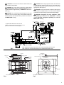
CAUTION: Locate pressure connector exactly
above the suction connection. Pressure and suction connectors must be exactly vertical or the rectangular cover
will be uneven in appearance.
CAUTION: Center of housing (the two nozzles)
should be 10” BELOW water level for maximum efficiency.
NOTE: The list below shows all parts that ARE NOT
USED IN A FIBERGLASS/VNYL LINER INSTALLATION:
1. Cover Plate
2. Stud Bolt M8 x 80
3. Washer M8
4. Nut M8
0.25"
CAUTION: Gasket with knobs (part #26) goes BEHIND pool wall.
CAUTION: Clamping ring gasket (part #27) goes in
FRONT of pool wall. A good RTV silicone may be used
with gasket when mounting jet housing, but in most cases
is not necessary. Installer should decide whether or not
silicone is necessary.
part #30
part #31
part #32
part #33
Air Control
1.7"
0.5"
Water Level
Top
30°
10.0"
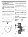
The template provided should be used to mark and drill
the holes as shown in fig. 6. For the air regulator, one 1/2”
hole must be provided, preferably along the vertical axis,
approximately 4” ABOVE the water line.
.0"
3"
13.
"
.7
Use the two countersunk bolts M6 (part #10), two nuts
(part #11), and two washers (part #12) to fasten holder
to wall with bolt heads on poolside and nuts on backside.
This will keep the holder attached to pool wall for liner
installation or replacement. NOTE: Gasket (part #13)
with larger holes on the outside, fits over screw heads
between inside of pool wall and liner. This gasket may be
held in place with silicone during liner installation.
14
14
For Liner pools only, two additional 1/4” holes need to
be made on either side of the 1/2” hole. (see Fig. 6)
0.3"
15°
Fig. 6 Cutout in Pool Wall 13.3” for BADUJET Housing.
The two holes at 15o from the vertical axis and the two
holes at the air regulator will allow both housing and air
regulator to be mounted with countersunk screws (M8 jet
housing / M6 air regulator) before the liner is place.
5a. Removal of Liner
When replacing liner or removing liner for repairs; remove
4 bolts (part #95) which hold square cover (part #93) to
jet housing. Remove all bolts (part #29) except top two,
which hold the clamping ring (part #28) and gasket (part
#27) to jet housing. Back out the two remaining bolts approximately halfway and check for any movement of jet
housing from the wall. (NOTE: If the two counter sunk
bolts (part #98) which hold the jet housing to the wall were
installed, the jet housing should not move, and the two
8
remaining bolts can be removed.) Remove one of the remaining two bolts and slide clamping ring (part #3) to the
side. Replace all the bolts before removing the last bolt.
Remove or replace liner. Reverse process to install liner.
NOTE: When replacing clamping ring and bolts: locate
bolt heads under liner, make small cut on liner at the bolt
heads and push liner over bolt head.