1
23
03/10 Rev. 5.04-01
SERVICE MANUAL
Service Electronics
64-xx Gen. 2 – DPM Gen. 2 – ALX 92x Gen. 2
USI testbox
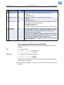
Application
Simulating USI inputs
Checking USI outputs
Monitoring of drive signals sent by the system control
Aid for setting up the machine.
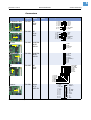
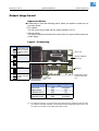
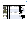
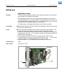
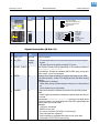
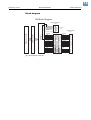
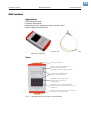
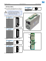
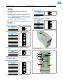
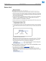
Fig. 12: Left side: USI testbox (A2739); right side: connecting cable (A2842). Both parts are
required for application.
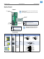
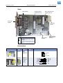
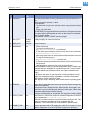
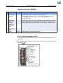
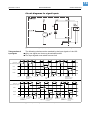
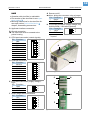
View
Connection to the USI
Survey of the voltage supply at the
D-Sub connector of the USI
(The test box needs 5 V supply voltage!)
Survey of in- and outputs at the
D-Sub connector of the USI
Simulation of the 4 inputs at the
D-Sub connector of the USI
(4 pushbuttons)
Simulation of the 4 internal inputs at the
CN300 connector of the USI (from vers. 4 on)
(4 switches)
z0175E.CDR
•
•
•
•
Optional connection of a customer control unit
or product sensor (monitoring)
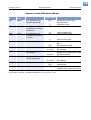
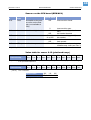
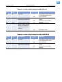
Fig. 13: Operating parts and connections of the USI testbox.