1
Installation, Operation and Service Manual
LKP Series
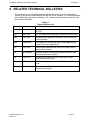
8. RELATED TECHNICAL BULLETINS ___________________________________ 31
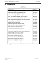
9. DRAWINGS _______________________________________________________ 33
DRAWINGS & TABLES
Figure 5.1
Figure 5.2
Figure 5.3
Figure 5.4
Figure 6.1
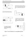
General Guidelines for Locating Measuring Heads ................................................. 10
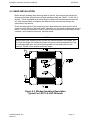
Window Insulation Description Typical For LKP-15 & LKP-30 Heads .................... 11
Measuring Head Orientation. .................................................................................. 18
Magnetic Centering ................................................................................................ 19
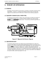
Magnetic Null Detector Diagram ............................................................................. 21
Table 4.1
Table 4.2
Table 5.1
Table 5.1
Table 7.1
Table 8.1
Table 9.1
LKP Series 4 Channel Specifications ......................................................................... 7
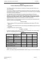
Typical Error At Zero Bus Current .............................................................................. 8
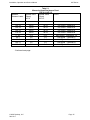
Measuring Head Resistance Chart LKP-6 & LKP-12 .............................................. 15
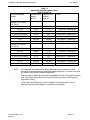
Measuring Head Resistance Chart LKP-15 & LKP-30 ............................................. 16
Spare Parts List ....................................................................................................... 29
Technical Bulletin List .............................................................................................. 31
Drawing List ............................................................................................................. 33
© 2010 DynAmp, LLC
041610 J
Page xiv