1
GENUINE PARTS
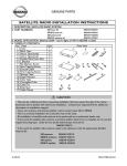
SATELLITE RADIO INSTALLATION INSTRUCTIONS
1. DESCRIPTION: SATELLITE RADIO SYSTEM
2. PART NUMBERS:
XM tuner kit
Sirius tuner kit
XM antenna kit
Sirius antenna kit
Antenna feeder cover
N-BUS extender harness
999U9-NV003
999U9-NV004
999U9-VQ006
999U9-VQ007
999U9-ZQ000
999U9-EP000
3. MODEL APPLICATION: 350Z 2-Door Coupe (2004~)
4. TUNER KIT CONTENTS:
No.
Part
Qty
1
2
3
4
5
6
7
8
9
10
11
12
13
14
15
16
17
Tuner
Black Tape
Velcro Tape (hook)
Velcro Tape (loop)
Spacer
Bracket
M4 Screw
5mm Tapping Screw
Ground Cable
6mm Tapping Screw
Sponge Tape
Edge Protector
Clear Tape
Corrugated Tube
Cable Tie
Butyl Gum
Cable Clamp
1
2
2
2
1
2
4
4
1
1
14
1
4
1
4
2
4
Part view
1
2
4
3
5
6
11
12
16
17
7
13
8
9
14
10
15
! CAUTION
This can be a difficult and time consuming installation that may require the skill of the master technician who is
familiar with electronics installation. Contact your regional DTS for additional information on installation support.
Tuner unit, antenna, and antenna splitter must be same brand, XM or SIRIUS
This is a universal installation kit so all parts may not be used.
Re-installation of satellite radio antenna to be performed by an authorized dealer only.
In the event the satellite radio antenna or antenna splitter needs to be re-installed, do not use the original
mounting tape. Order the low profile antenna adhesive tape kit:
999U9-VQ010
In the event the satellite radio antenna needs to be replaced, order the appropriate Satellite Antenna Kit.
XM LPA 11’ service kit
999U9-VQ012
SIRIUS LPA 11’ service kit
999U9-VQ013
XM splitter
999U9-VQ004
SIRIUS splitter
999U9-VQ005
07/26/04
284-9798-50-L1
350Z Coupe
5. TOOL & MATERIAL REQUIRED:
1.
2.
3.
4.
5.
6.
Phillips screw driver
Clip remover
Electrical tape
Tape measure
Masking tape
Bitumen wax
(999MP-9G001P)
or equivalent
7. 50/50-alcohol/water solution
8. 10mm socket
9. 1/4” drive ratchet
10. Die grinder with cutoff wheel
(wheel no larger than 3” diameter)
11. PGF stick for antenna cable routing
2~3mm
15~20mm
12. Plastic pry bar (J-46534 or equivalent)
6. STANDARD CONNECTION METHOD
Satellite Antenna
Antenna Splitter
Vehicle Harness
Curry
Satellite Tuner
Unit
Green
A16
A16
Ground Cable
Ground
07/26/04
2 of 11
If the tuner unit is installed using the
bracket and the bracket is screwed onto
the metal part of the car body where a
ground can be made, it is not necessary
to use the ground cable.
284-9798-50-L1
350Z Coupe
7. INSTALLATION OUTLINE
Pre-wired N-BUS cable
N-BUS extender harness
Satellite antenna
Tuner unit
Antenna splitter
8. VEHICLE PREPARATION
(1) Record the customer radio preset.
(2) Apply parking brake.
(3) Make sure that the shift lever is engaged in the “P” position.
(4) Open the trunk lid.
(5) Open the windows completely.
(6) Disconnect the battery negative terminal to prevent short circuits during installation.
! CAUTION
Before disconnecting the battery negative terminal, lower the windows completely.
! CAUTION
Do not damage vehicle or parts. Refer to Service Manual for proper removal and reinstallation.
07/26/04
3 of 11
284-9798-50-L1
350Z Coupe
(7) Remove the following trunk interior trim parts as
shown in figure 1.
1. Luggage finisher lower (center)
2. Luggage side finisher upper (RH)
3. Luggage floor carpet
4. Spare tire cover
5. Spare tire (not shown in figure 1)
6. RH trunk bracket
7. Tool box
8. Clips
9. Strut cover upper (RH)
10.Disengage 3 clips on (RH) side of strut cover rear.
(Not necessary to remove completely)
11.Luggage side finisher (RH)
Disengage (3) clips
figure 1
07/26/04
4 of 11
284-9798-50-L1
350Z Coupe
9. Antenna Installation
9-1. Notch cutting
1. Remove the weather strip at the top right of trunk.
2. Place a strip of masking tape starting from the (RH)
hatch hydraulic strut mount to the back door of the
vehicle make sure that is straight as possible. And
place a 100mm strip of masking tape along the
gutter lip as shown in figure 2.
3. Measure 110mm beginning from the (RH) hatch
hydraulic strut mount. Place a mark on the masking
tape. This measurement will be used as a reference
to mark the right point of the notch on the masking
tape along the gutter lip. figure 2
4. The notch will measure 15mm wide to the left of the
refrence mark by 3mm deep. figure 2
! CAUTION
Do not damage vehicle parts during notch cutting
procedure.
Protect window and trim with fender cover or similar.
5. Cut a notch on the gutter lip with a die grinder.
6. Remove burrs or sharp edges from the notch.
7. Apply rust-proof to cut surface.
figure 2
9-2. Feeder cover installation
1. Clean roof area with 50/50 alcohol water solution.
! CAUTION
Do not touch or contaminate the cleaned roof or the
adhesive tape on the antenna to prevent the adhesion
strength from being reduced.
figure 3
2. Cut the tail flap portion off along the antenna
recessed line at the 90 degree bend. figure 3
! CAUTION
Do not damage antenna cable.
3. Place antenna 2” from edge. figure 4.
4. Lay feeder cover on roof in final installed position.
Make sure feeder cover is over antenna cable.
figure 4
5. Center feeder cover on vehicle roof. Make sure the
lip edge is flushed with the roof sheetmetal in the
channel.
6. Use two 6” strips of masking tapes and place
3” away from both sides of the notch. figure 4
7. Position antenna on the roof with the tail flush to
the notch on feeder cover.
8. Check visually and make sure that the antenna is
centered and straight.
9. Hold down antenna tail to prevent movement.
figure 4
! CAUTION
Do not stretch the tail when installing the tail.
07/26/04
5 of 11
284-9798-50-L1
350Z Coupe
10. Raise antenna head and peel off the tape protector.
figure 5
! CAUTION
In case of ambient temperature below 20ºC (70ºF), it
is required to warm the tape and mounting surface
with a heater to minimum of 20ºC (70ºF).
figure 5
11. Properly place the antenna and then apply a 20 lbs.
of downward force for 20 seconds while rocking
hand back and forth across the top of the antenna to
assure proper adhesion. figure 6
! CAUTION
During antenna mounting process, make sure rubber
dust seal "flares" outward while downward force is
applied.
Satellite antenna
figure 6
figure 7
Rear glass
12. Remove two strips of tape and feeder cover.
13. Remove tape protector from antenna tail. With hand
pressure, apply downward force to full length of the
tail to assure proper adhesion. figure 5
14. Loosely, fit the cover over the installed antenna over
the antenna tail. Make sure feeder cover orientation
is the same as shown in figure 4
15. Peel back the center tape 3"-4” from the notch area.
16. Hold feeder cover vertically, when installing the
antenna cable to avoid slack. Attach 2-3" of antenna
feeder. figure 7
17. Confirm that feeder cover can be installed by placing
it on vehicle.
18. Peel off the rest of the center tape liner and install
the antenna feeder in the center channel.
19. Route the feeder under the right roof trim. figure 8
20. Peel off 3-4" of both outer double sided tapes at the
center near the notch and ends. Make sure that both
liners point outward and do not interfere with the rest
of the feeder installation.
21. Install the feeder cover with the lip firmly against the
roof edge. Make sure that the ends of the feeder
cover butt up against rubber of roof trim.
22. Pull off the outer tape liner from the lip side and apply
downward pressure from notch towards one end.
Then, apply downward pressure from notch towards
opposite end.
23. Pull off remaining tape liners and firmly apply
pressure from the ends toward the center.
FRONT
Roof trim
07/26/04
Roof
figure 8
6 of 11
284-9798-50-L1
350Z Coupe
24. Before installing, cut the 14 corrugated tube to
198mm.
25. Attach the 14 corrugated tube to the antenna cable
and tuck 4mm (5/32”) under the roof side molding
refer to figure 9.
26. Route the 14 corrugated tube and antenna cable
to the notch.
27. Starting 25mm (1”) from the top of the corrugated
tube where the antenna cable come out from the
roof side molding, attach (4) 17 cable clamps
equally spaced along a flat smooth surface that
travels into the notch area. (Alternate tab direction)
refer to figure 10.
Rear hatch
14 Corrugated tube
Tuck 4mm under
roof side molding
Passenger roof
side molding
! CAUTION
Keep cable clamps as far away from the gutter lip as
possible in order to avoid interference with weather
strip.
Make sure to apply cable clamps to smooth flat sur
face.
Do not attach cable clamps on sealer or spot welds.
figure 9
28. Secure the tubing by inserting the tubing into
the 17 cable clamps and bending the tabs
down.
Cable clamp
figure 10
07/26/04
7 of 11
284-9798-50-L1
350Z Coupe
Top right section of trunk
NOTE
The following steps 29 to 36 are critical to
water leak, therefore must be followed strictly.
29. Attach the 12 edge protector over the notch.
30. Use alcohol wipe included in the kit to clean surrounding area before application of clear tape.
31. Route the antenna cable over the 12 edge protector.
! CAUTION
Make sure the antenna cable is seated in the channel
of the edge protector.
figure 11-1
figure 11-2
figure 11
32. Position the clear tape above the notch without peeling off the liner to estimate the correct position for
the small amount of 16 butyl gum.
33. Before applying the 13 clear tape, apply a small
amount of 16 butyl gum to the bottom side of
antenna cable to hold antenna cable at the radius
corner where antenna cable will enter 13 clear tape.
34. Do not peel off the entire clear tape protector. Pull
the clear tape protector back 10 mm (3/8"). Then
apply 10mm clear tape to the horizontal flat surface
of the gutter. Then slowly massage the clear tape
with a PGF stick till you have reached the corners.
Make sure that the 13 clear tape does not wrinkle.
Apply the same technique to the vertical surface.
Then fold the tape over and apply the technique
once more. This should leave a smooth surface on all
three sides. figure 11-1 & figure 11-2
35. Wedge the straight part of the plastic pry bar
between the plastic trim and metal lip. Gently push
pry bar away from you to provide room to smooth out
the back surface of the clear tape. figure 11
! CAUTION
In order to stop water from entering the trunk
through the 13 clear tape, the clear tape must have
complete (100%) wet out 5 - 10mm (1/4” - 3/8”) on
all three sides of peripheral boundary and no wrinkle.
(figure 11-1)
Ensure antenna cable is entering the clear tape at
the radius corner.
07/26/04
8 of 11
284-9798-50-L1
350Z Coupe
36. Apply 16 butyl gum at both ends of the clear tape.
The butyl gum should fit into both corners to cover
the antenna cable and the opposite end of the clear
tape. figure 11-1
(RH) Trunk view
Trunk trim mounting hole
! CAUTION
Butyl gum must be placed across cable for good
water seal.
37. Route the antenna cable along the existing channel
that runs above the panel clip holes. figure 12
! CAUTION
Do not cover trim mounting holes with antenna cable
or clear tape.
Antenna cable
13 Clear tape
RH strut cover
figure 12
38. Secure antenna cable into existing channel
with 2 pieces of 13 clear tape shown in figure 12.
39. Route the antenna cable under the (RH)
rear quarter panel over hang. Secure antenna cable
with 11 sponge tape in two places refer to
figure 13.
40. Route antenna cable and secure the cable to the
black bracket above the (RH) rear tail light assembly
with sponge tape. figure 13
(RH) Trunk view
Trunk trim mounting holes
11 Sponge tape
07/26/04
figure 13
9 of 11
284-9798-50-L1
350Z Coupe
10. TUNER INSTALLATION
1.
Remove the factory tape to release N-BUS cable.
! CAUTION
In case of ambient temperature below 20ºC (70ºF), it
is required to warm the tape and mounting surface
with a heater to minimum of 20ºC (70ºF).
2.
3.
4.
5.
Plug the N-BUS cable extender harness plug into
the vehicle N-BUS cable. figure 14
Route the N-BUS cable extender harness around
the wheel well away from exposed bolts and secure
with sponge tape as shown in figure 14.
Clean the back of the 1 tuner and the rear trunk
panel with 50/50 alcohol/water solution where the
tuner is to be attached.
Cut one (1) 5 spacer 100mmx120mm (4") x (4.8")
! CAUTION
Make sure to clean the tuner with 50/50 alcohol/water
solution before attaching spacer and Velcro.
figure 14
6.
Attach the 5 spacer to the top part of the tuner.
figure 15-1
7. Also attach the 3 Velcro hook and 4 loop
together then peel tape protector on Velcro side.
Attach the Velcro strip to the bottom of the tuner as
shown in figure 15-1.
8. Place the tuner between both bolts that secure the
(RH) trunk bracket. Peel tape protector on Velcro
loop side. Attach Velcro strip to the bottom panel of
the trunk shown in figure 15-2.
9. While reinstalling (RH) trunk bracket use the right
bolt to secure the ground connection for the
satellite tuner unit. figure 16
10. Apply firm pressure to the satellite tuner.
11. Ensure tuner is mounted 2mm towards RHS from
floor hump to prevent vibration noise. figure 15-3
figure 15-1
figure 15-3
figure 15-2
07/26/04
10 of 11
284-9798-50-L1
350Z Coupe
10-1. Tuner wiring
1. Insert antenna splitter cable connectors into
corresponding tuner terminals.
2. Clean top of tuner with 50/50 alcohol/water solution.
3. Peel off tape protector from the splitter. Place the
splitter on the top of the tuner. Secure the antenna
splitter to the tuner by applying downward force with
hand pressure. figure 16.
4. Route the antenna cable to the splitter location.
Secure with sponge tape 11 as shown. figure 15
5 Leaving enough length for the splitter connection,
neatly coil excess antenna cable to create a loop
100mm (4”) in diameter.
RH rear trunk bracket
! CAUTION
11 Sponge tape
Splitter
connectors
Antenna
splitter
Antenna coil
100mm (4”) diameter
figure 16
Do not kink antenna cable.
Do not change diameter of the antenna loop.
6. Connect the antenna cable connector to the antenna
splitter.
7. Attach the antenna cable loop to the back of the
trunk panel with sponge tape at two locations.
figure 16
8. Connect the N-BUS cable connector to the
corresponding tuner terminal.
11. OPERATION CHECK
(1) Connect the battery negative terminal.
(2) Turn vehicle ignition switch to the “ACC” position.
(3) Turn radio on then select satellite radio mode.
Acquiring (Sirius) or loading (XM) will display for a
while. If not, move vehicle to outside and try again.
(4) Tune to preview channel ( XM: channel ”1” / SIRIUS: channel ”184” ) to make sure receiving preview
channel correctly.
(5) Confirm proper audio operation. ( AM / FM / TAPE /
CD )
12. REINSTALLATION OF REMOVED PARTS
(1) Reinstall all removed vehicle parts referring to the
service manual for the vehicle.
(2) After reinstalling the weather stripping spread butyl
gum over the antenna and weather stripping to close
any gaps and improve the seal. figure 17
(3) Be sure to engage all clips on parcel trunk finisher.
(4) Clean vehicle interior.
figure 17
13. FINAL INSPECTION
(1) Inspect vehicle interior and exterior for damage.
(2) Confirm proper operation of vehicle systems.
(3) Reset radio presets to the recorded settings.
07/26/04
11 of 11
284-9798-50-L1