1
PBS 2.1.002: LCM_BACK board (in LCM container)
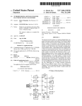
Schematic diagramme of LCM_BACK board
The main functions of the LCM_BACK board are:
●
●
●
Distribution, inside the LCM container, of all signals from or to each board inserted inside
the LCM_CRATE.
Distribution of electrical power (+5V, +3.3V, +2.5V, +1.8V, +12V, +48V) and common
return, all these power signals come from the POWER_BOX fixed on the LCM_CRATE ,
which converts the 400V DC to all values needed inside the LCM.
Interfaces between optical modules signals and the electronics boards (ARS_MB,
POWER_BOX and COMPASS_MB).
Interfaces inside the LCM are:
●
●
●
●
Each board inserted in the LCM_CRATE is connected to the LCM_BACK by its rear
connector (24, 48, or 96 pins). The location of each board is fixed in order to optimise
parallel development and connections to the EMC.
4 connectors provide the interface with the optical modules and the LED beacon.
1 connector makes the interface with other containers for RS232 and the second RS485
serial bus, this connector provides the test signal for the LCM_DAQ/SC board (external test
trigger signal). This connector drives also the main RS485 serial bus for all boards inserted
inside the LCM_CRATE in order to test slow-control without the LCM_DAQ/SC board.
The boards inserted inside the LCM_CRATE are (in the maximal configuration):
COMPASS_MB, ARS_MB for OM1,2 and 3, ARS_MB for LED beacon,
LCM_DWDM, LCM_SWITCH, MLCM_BIDICON, LCM_DAQ/SC,
LCM_CLOCK, LCM_TRIG, LCM_ACOUST1,2 and 3 and POWER_BOX.
Page 5-28