1
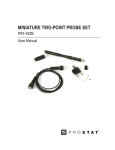
PRS-812 Resistance Meter
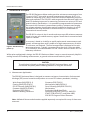
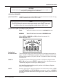
AUTO Mode 1: Auto Exponential Display 1.0EXX plus Ω indicators
AUTO Mode 2: Auto Display in Ω, KΩ, MΩ, GΩ and TΩ indicators
AUTO Mode 1 is the default functional mode when the PRS-812 is powered up. To change to AUTO
Mode 2, simply press the MODE button once. The AUTOMATIC modes are used in measurements
where the following attributes are desired:
→
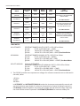
Automatic Test Voltage selection and control from 0.01 to 100 volts
→
Automatic resistance scale control from 0.1 ohm to 1.0x10¹² ohms (200 TΩ)
→
Automatic Electrification Period timing based on the instrument’s measurement capabili-
ties and industry standards for measurement of ESD controlled materials.
In AUTOMATIC Modes, the PRS-812 performs the following functions during the Measurement Test
Cycle once the TEST button is pressed:
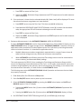
1.
2.
3.
4.
Resets the RESISTANCE RANGE to minimum, i.e., 0.1Ω
Sets TEST VOLTAGE to <10 volts (millivolts), and applies initial voltage to material under test
Resets the ELECTRIFICATION PERIOD timer to 0 seconds, then starts timer
During Measurement Test Cycle:
a. Automatically adjusts RESISTANCE RANGE in accordance with material resistive characteristics
b. Automatically adjusts TEST VOLTAGE in accordance with material resistive characteristics
and industry standards
c. Automatically adjusts ELECTRIFICATION PERIOD in accordance with material resistive characteristics and industry standards
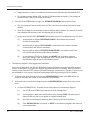
5. At completion of Test Cycle, displays and HOLDS final resistance measurement, test voltage,
order of magnitude (LED), analog scale & multiplier, and electrification time at end of electrification period.
D. General Automatic Mode Procedures
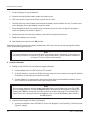
1. Attach the desired test leads to the fixture, electrodes or points to be measured
NOTE
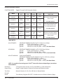
The standard Prostat 10 foot test leads are intended for measurements up to
the 1012 ohm range. This is the maximum range of the PRS-812 for precision
resistance measurements
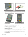
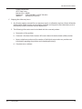
2. Slide the Battery Buss Cut Off to the ON position. This connects the 9V batteries to the instrument’s circuitry.
Rev. C / January 2012
23