1
4. For an MC68010, return DTACK before data verification. If data is invalid, assert
BERR on the next clock cycle (case 4).
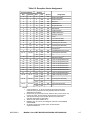
Table 5-6.
BERR and HALT Negation Results
Negated on Rising
Edge of State
Conditions of
Termination in
Table 4-4
Control Signal
N
Bus Error
BERR
HALT
•
•
or
or
•
•
Takes bus error trap.
Rerun
BERR
HALT
•
•
or
•
Illegal sequence; usually traps to vector number 0.
Rerun
BERR
HALT
•
BERR
HALT
•
•
or
•
BERR
HALT
•
or
•
none
Normal
Normal
N+2
Results—Next Cycle
Reruns the bus cycle.
•
May lengthen next cycle.
If next cycle is started, it will be terminated as a bus
error.
• = Signal is negated in this bus state.
5.7 ASYNCHRONOUS OPERATION
To achieve clock frequency independence at a system level, the bus can be operated in
an asynchronous manner. Asynchronous bus operation uses the bus handshake signals
to control the transfer of data. The handshake signals are AS, UDS, LDS, DS (MC68008
only), DTACK, BERR, HALT, AVEC (MC68EC000 only), and VPA (only for M6800
peripheral cycles). AS indicates the start of the bus cycle, and UDS, LDS, and DS signal
valid data for a write cycle. After placing the requested data on the data bus (read cycle)
or latching the data (write cycle), the slave device (memory or peripheral) asserts DTACK
to terminate the bus cycle. If no device responds or if the access is invalid, external control
logic asserts BERR, or BERR and HALT, to abort or retry the cycle. Figure 5-31 shows the
use of the bus handshake signals in a fully asynchronous read cycle. Figure 5-32 shows a
fully asynchronous write cycle.
ADDR
AS
R/W
UDS/LDS
DATA
DTACK
Figure 5-31. Fully Asynchronous Read Cycle
5-32
M68000 8-/16-/32-BIT MICROPROCESSORS USER'S MANUAL
MOTOROLA