1
Model 7600 Controller Users Manual
Revision B
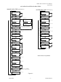
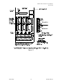
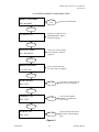
LCD OPERATOR INTERFACE MENU TREES
CHANNEL
MENUMENU
TREE (See
Section 2.2)
CHANNEL
TREE
SYSTEM MENU TREE (See Section 2.3)
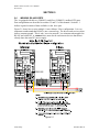
0 PCTLEL
0 PCTLEL
Measurement Name
Measurement Name
FUNCTION
Section 2.0
FUNCTION
F=NORM E=EDIT C1
UP/DN SELECTS CH
UP/DN SELECTS CH
Section 2.2.1
EDIT
A/D Cnts = 905
EDIT
0 PCTLEL
XXXX UNLOCKED
Edit = Cal Zero
NAME: John Doe
EDIT
Edit = Cal Mode
UP/DOWN
UP/DOWN
Edit = Unity
Resets Cal Mode
Scan Timer 10s
Edit = Cal Span
Channels 1234--
Alarm 2 Relay
Section 2.3.3
50.0=Cal Span
F
u
n
c
t
i
o
n
UP/DOWN
EUNITS D.P. = 0
Section 2.2.2
UP/DOWN
0.000 PCTLEL
Enter Zero Value
UP/DOWN
Section 2.3.2
UP/DOWN
These menus appear only if SENSOR is
selected in the Input Data From: menu.
Measurement Name
Section 2.3.1
UP/DOWN
51 PCTLEL
UP/DOWN
0.000=Cal Zero
Acknowledge On
UP/DOWN
Alarm Scan
Section 2.3.4
Priority Off
UP/DOWN
Alarm 1 Relays
Normal
UP/DOWN
Section 2.2.3
100.0 PCTLEL
F
u
n
c
t
i
o
n
Section 2.0
F=NORM E=EDIT SY
Section 2.3.5
Alarm 2 Relays
Enter 100% Value
Fail Safe
UP/DOWN
UP/DOWN
Alarm1 Horn-Off
Slave Port
20.00 Latch?N H
9600 Baud Id 1
UP/DOWN
UP/DOWN
Alarm 1 Delays
Section 2.3.6
Master Port
On 0s Off 0m
9600 Baud
UP/DOWN
Section 2.2.4
UP/DOWN
Alarm2 Horn-Beep
40.00 Latch?Y H
UP/DOWN
Alarm 2 Delays
On 5s Off 5m
Note: Arrows = Key Strokes
UP/DOWN
-5.000 Latch?N F
Section 2.2.5
% Fault
UP/DOWN
905 800 4000
Section 2.2.6
Input Min
Max
UP/DOWN
Input Data From:
Analog 12 Bit
UP/DOWN
Section 2.2.7
RTU 1
This menu appears only if Modbus is
selected in the Input Data From: menu.
Alias 33001
UP/DOWN
Copy Data To:
Section 2.2.8
Channel 1
Figure 2.2
UP/DOWN
Scott Safety
5
087-0018 Rev B