1
CHAPTER 2 / INTRODUCTION TO SOFTWARE DEVELOPMENT
2.3.2
17
Ports
Remember that embedded systems consist of computers embedded in larger systems. The
processor needs to sense the state of the larger system and environment, and control output
devices. The most basic way to do this is through one or more discrete signals, each of
which can be in one of two states (on or off). Microcontrollers have electrical pins which
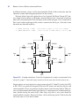
can be used to send electrical signals out from the device or can be used to accept electrical signals. These electrical pins can be grouped together and called ports. General purpose
digital I/O ports are the hardware which can be used to read from or write to the system
outside the microcontroller. The data of a port can be read from the outside through a port
data register. Its direction is set in a port direction register. Often a port is eight bits wide
and is assigned a number; i.e., Port 1. Some port pins are input only, some are output only,
and some can be configured to be input or output. If a pin is configurable, then its direction
is determined by a “direction” bit.
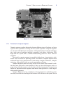
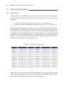
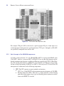
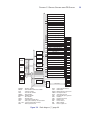
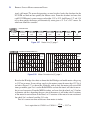
The GR-Sakura has nine defined Ports (PORT1-PORT5, PORTC-PORTE, and PORTJ)
with fifty-two I/O pins. Depending on the purposes these pins serve, they might have extra
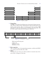
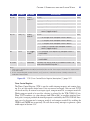
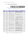
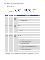
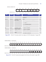
registers. Each port has a Port Direction Register (PDR), Port Output Data Register (PODR),
Port Input Register (PIDR), Open Drain Control Register (ODRy, y ⫽ 0, 1), Pull-up Resistor
Control Register (PCR), Drive Capacity Control Register (DSCR), and Port Mode Register
(PMR). The pins of a port may serve several purposes; for example, Port 4 pin 0 can be used
as a general purpose I/O pin, as an A/D converter input, or as an interrupt input. Depending
on the purposes these pins serve, they might have extra registers.
Certain other registers called Port Function Registers are also present. These registers
are associated with special features of the RX63N micro-controller such as USB, CAN, etc.
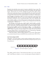
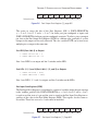
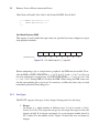
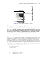
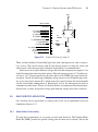
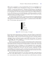
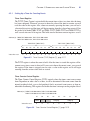
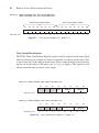
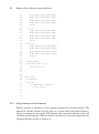
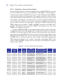
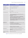
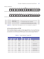
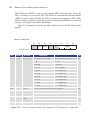
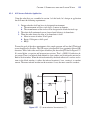
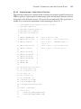
Port Direction Register (PDR)
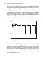
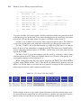
This register, as the name suggests, is used to set the port direction (input or output) of a
pin. PDR is a read/write register. Each bit of the Port Direction Register represents a pin on
the specified port.
Value after reset:
B7
B6
B5
B4
B3
B2
B1
B0
0
0
0
0
0
0
0
0
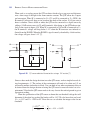
Figure 2.5 Port Direction Register [1], page 661.
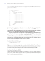
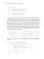
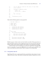
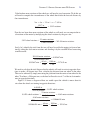
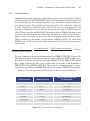
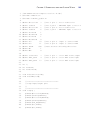
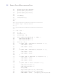
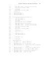
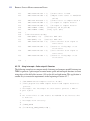
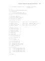
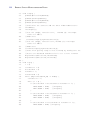
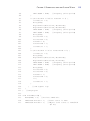
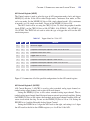
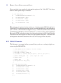
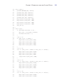
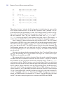
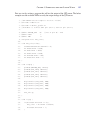
The ‘iodefine_gcc63n.h’ file has C code constructs that make it easy to access each port
with C code. Each port is defined as a structure and each register of the port is defined as a